 ★ HARDWARE Manual ★ VDP1 User's Manual
FBCR | bit15 | bit14 | bit13 | bit12 | bit11 | bit10 | bit9 | bit8 | bit7 | bit6 | bit5 | bit4 | bit3 | bit2 | bit1 | bit0 |
|---|---|---|---|---|---|---|---|---|---|---|---|---|---|---|---|---|
| 0 | 0 | 0 | 0 | 0 | 0 | 0 | 0 | 0 | 0 | 0 | EOS | DIE | DIL | FCM | FCT |
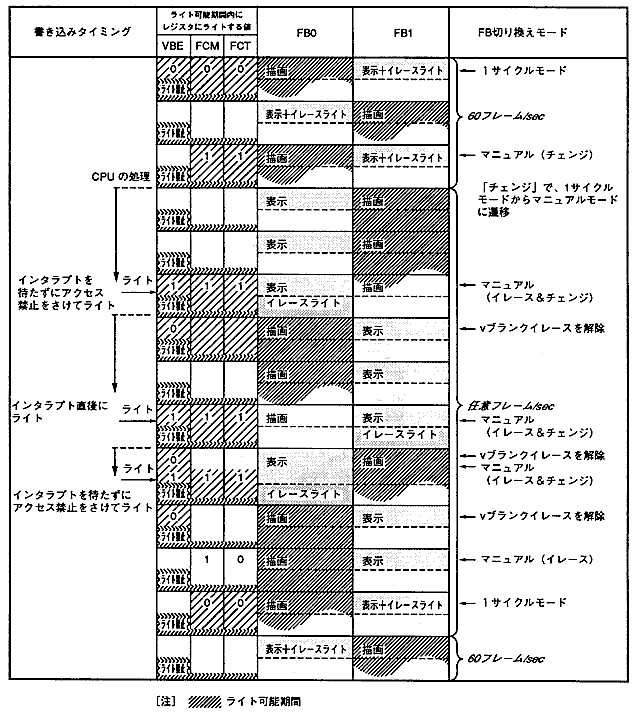
VBE | FCM | FCT | Switching mode | Switching time |
|---|---|---|---|---|
0 | 0 | 0 | 1 cycle mode | Change every 1/60 second |
0 | 0 | 1 | Setting prohibited | − |
0 | 1 | 0 | Manual mode (erase) | Erase in the next field |
0 | 1 | 1 | Manual mode (change) | Change in the next field |
1 | 0 | 0 | Setting prohibited | − |
1 | 0 | 1 | Setting prohibited | − |
1 | 1 | 0 | Setting prohibited | − |
1 | 1 | 1 | Manual mode (erase & change) | Erase with V blank, |
Set value * 1 | * 2 | * 2 | Frame buffer switching mode | Switching time | |
FCM | FCT | ||||
0 | 0 | drawing | Display + erase light | 1 cycle mode | 60 frames / sec |
Display + erase light | drawing | ||||
drawing | Display + erase light | ||||
Display + erase light | drawing | ||||
1 | 1 | drawing | Display + erase light | Manual mode (change) * 3 | |
display | drawing | 20 frames / sec | |||
1 | 0 | display | drawing | Manual mode (erase) * 4 | |
1 | 1 | Display + erase light | drawing | Manual mode (change) * 4 | |
drawing | display | ||||
1 | 0 | drawing | display | Manual mode (erase) * 5 | |
0 | 0 | drawing | Display + erase light | 1 cycle mode | |
Display + erase light | drawing | 60 frames / sec | |||
drawing | Display + erase light | ||||
DIE | DIL | Interlaced mode | Drawing after the next frame change |
0 | 0 | Non-interlaced / | All line drawing |
0 | 1 | Setting prohibited | − |
1 | 0 | Dense interlace | Draw only even (EVEN) lines |
1 | 1 | Dense interlace | Draw only odd (ODD) lines |
● Display of single-dense interlace ● Display of double-dense interlace
┌────────┐ ┌────────┐
│ 0 line ├────────┐ │ 0 line ├────────┐
├────────┤ 0 line │ ├────────┤ 1 line │
│ 1 line ├────────┤ │ 2 lines ├────────┤
├────────┤ 1 line │ ├────────┤ 3 lines │
│ 2 lines ├────────┤ │ 4 lines ├────────┤
├────────┤ 2 lines │ ├────────┤ 5 lines │
│ 3 lines ├────────┤ │ 6 lines ├────────┤
└────────┤ 3 lines │ └────────┤ 7 lines │
└────────┘ └────────┘
・ It looks like 256 lines vertically ・ It looks like 512 lines vertically
・ Frame change every 1/60 second ・ Even number in each frame buffer
Draw the same twice or draw only (or odd) lines
Frame change every 1/30 second
(Instructed by the CPU using a 1/60 second signal)
EOS | Even / odd coordinate selection bits |
0 | Sampling only even-coordinated pixels |
1 | Sampling only odd-numbered pixels |
★ HARDWARE Manual ★ VDP1 User's Manual