 ★ HARDWARE Manual ★ VDP1 User's Manual
EWDR | bit15 | bit14 | bit13 | bit12 | bit11 | bit10 | bit9 | bit8 | bit7 | bit6 | bit5 | bit4 | bit3 | bit2 | bit1 | bit0 |
|---|---|---|---|---|---|---|---|---|---|---|---|---|---|---|---|---|
| Erase light data | ||||||||||||||||
EWDR | bit15 | bit14 | bit13 | bit12 | bit11 | bit10 | bit9 | bit8 | bit7 | bit6 | bit5 | bit4 | bit3 | bit2 | bit1 | bit0 |
|---|---|---|---|---|---|---|---|---|---|---|---|---|---|---|---|---|
| Even X coordinate erase light data | Odd X coordinate erase light data | |||||||||||||||
EWLR | bit15 | bit14 | bit13 | bit12 | bit11 | bit10 | bit9 | bit8 | bit7 | bit6 | bit5 | bit4 | bit3 | bit2 | bit1 | bit0 |
|---|---|---|---|---|---|---|---|---|---|---|---|---|---|---|---|---|
| 0 | Upper left coordinate X1 | Upper left coordinate Y1 | ||||||||||||||
EWRR | bit15 | bit14 | bit13 | bit12 | bit11 | bit10 | bit9 | bit8 | bit7 | bit6 | bit5 | bit4 | bit3 | bit2 | bit1 | bit0 |
|---|---|---|---|---|---|---|---|---|---|---|---|---|---|---|---|---|
| Lower right coordinate X3 | Lower right coordinate Y3 | |||||||||||||||
System register value | 16bit / pixel | 8bit / pixel | ||||
High resolution | Rotation 8 | |||||
Upper left coordinate X1 | Lower right coordinate X3 | Upper left coordinate X1 | Lower right coordinate X3 | Upper left coordinate X1 | Lower right coordinate X3 | |
0 | 0 | Setting prohibited | 0 | Setting prohibited | 0 | Setting prohibited |
1 | 8 | 7 | 16 | 15 | 16 | 15 |
2 | 16 | 15 | 32 | 31 | 32 | 31 |
: | : | : | : | : | : | : |
31 | 248 | 247 | 496 | 495 | 496 | 495 |
32 | 256 | 255 | 512 | 511 | Setting prohibited | 511 |
33 | 264 | 263 | 528 | 527 | Setting prohibited | Setting prohibited |
: | : | : | : | : | : | : |
40 | 320 | 319 | 640 | 639 | : | : |
: | : | : | : | : | : | : |
43 | 344 | 343 | 688 | 687 | : | : |
44 | 352 | 351 | 704 | 703 | : | : |
: | : | : | : | : | : | : |
62 | 496 | 495 | 992 | 991 | : | : |
63 | 504 | 503 | 1008 | 1007 | : | : |
64 | Setting prohibited | 511 | Setting prohibited | 1023 | : | : |
65 ~ | Setting prohibited | Setting prohibited | Setting prohibited | Setting prohibited | Setting prohibited | Setting prohibited |
Figure 4.2 Erase light area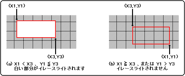
{(Number of pixels in one raster)-200} x {(Number of rasters in one field)-(Number of display rasters)}Screen mode | Number of horizontal pixels | Number of pixels in one raster | Number of rasters in one field |
NTSC | 320 | 1708 | 263 |
PAL | 352 | 1820 | 313 |
31KC | − | 852 | 525 |
HDTV | − | 848 | 562 |
Screen mode | Resolution (horizontal x vertical) | Number of pixels available |
NTSC | 320 x 224 | 58812 |
320 x 240 | 34684 | |
352 x 224 | 63180 | |
352 x 240 | 37260 | |
PAL | 320 x 224 | 134212 |
320 x 240 | 110084 | |
320 x 256 | 85956 | |
352 x 224 | 144180 | |
352 x 240 | 118260 | |
352 x 256 | 92340 | |
31KC | 320 x 480 | 29340 |
HDTV | 352 x 480 | 53136 |
★ HARDWARE Manual ★ VDP1 User's Manual