HARDWARE ManualSCSP User's Manual
BackForward
SCSP User's Manual / 4.2 Sound Source Register

■ Loop control register

KYONEX (W) : KeY ON EXecution
Every time "1B" is written, KEY_ON, OFF of all slots is executed.

KYONB (R / W) : KeY ON Bit
Register KEY_ON, OFF. If you want to turn on KEY_ON at the same time, set "KYONB" of the slot you want to turn on to "1B".

Functions of KYONB bit
Register 0 = KEY_OFF
1 = Register KEY_ON

About KYONEX Bit and KYONB Bit

"KYONEX" and "KYONB" exist in each slot. The sequence of KEY_ON and KEY_OFF is shown in Figure 4.2.
"KYONEX" does not need to write "0B" after writing "1B". "1B" in any slot works for all slots, so you don't have to set it to "1B" in a particular slot.

Figure 4.2 KEY_ON and KEY_OFF functions

SBCTL [1: 0] (R / W); Source Bit ConTroL
Specifies the bit inversion operation excluding the sign bit of the sound input data.
The inversion function of the bit in which "1B" is written is enabled.

SBCTL function
SBCTL0: Invert specification other than the sign bit of the source waveform data
SBCTL1: Invert the sign bit of the source waveform data

SSCTL [1: 0] (R / W); Sound Source ConTroL
Specifies the data to use as sound input data. Write "0B" to pronounce using the waveform data on the sound memory. When this register is set to "1B", noise is output from the slot (LFO attached to each slot) for which the setting was made.
Figure 4.3 shows the relationship between the block diagram and the LFO related to noise generation when "SSCTL" = "1B", with the ALFO attached.

Figure 4.3 Relationship between block diagram and LFO related to noise generation
* ALFO is attached here.

Each slot uses the output of the LFO's noise oscillator to output noise. At this time, the LFO parameters ("LFORE", "LFOF", "ALFOWS", "ALFOS", "PLFOWS", "PLFOS" in Fig. 4.3 have no effect on the noise as audio data.
Also, as shown in Fig. 4.3, when the LFO is used for low frequency modulation and the waveform selection of the LFO is set to noise (ALFOWS = "3H" or PLFOWS = "3H"), the reset by "LFORE" is not applied. Hmm. Also, the frequency cannot be changed. This means that when selecting noise, the LFO can select the waveform, but not the other parameters.

Functions of SSCTL
00B = External DRAM data
01B = Internally generated data (noise)
10B = Internally generated data (ALL "0")
11B = Not available

SA [19: 0] (R / W); Start Address
When using the waveform data in memory for pronunciation, specify the start address of the waveform data in byte addresses. However, if the waveform data is in "16-bit PCM format" ("PCM8B" = "0B"), be sure to set the value of the least significant bit (SA0) of the register to "0B".

LSA [15: 0] (R / W); Loop Start Address
The loop start address of the sound data is represented by the number of samples from "SA".

LEA [15: 0] (R / W); Loop End Address
The loop end address of the sound data is represented by the number of samples from "SA".

PCM8B (R / W); PCM 8Bit
Specify the word length (format) of the waveform data.

Sound data type (PCM8B function)
0B = 16-bit PCM data 2'S complement
1B = 8-bit PCM data 2'S complement

LPCTL [1: 0] (R / W) LooP ConTroL
Set the loop format.

Loop type (LPCTL function)
00B = Loop OFF
01B = normal loop
10B = reverse loop
11B = alternative loop

Loop processing or sound memory access ends under one of the following two conditions.

  1. When the amount of attenuation is maximized after release.
  2. When the read point reaches the loop endpoint when the loop is OFF.

When using the normal loop and reverse loop, the data corresponding to "SA + LSA" (loop start address) and the data corresponding to "SA + LEA" (address at the end of the loop) in the waveform data have the same value. Please set to. The alternative loop can be matched to the pitch of the normal and reverse loops in the same way.
Figure 4.10 shows a concrete example of the loop type.

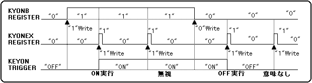
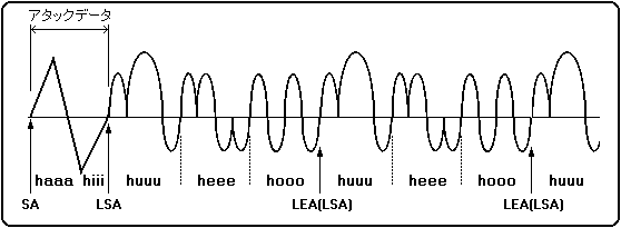
Figure 4.4 Loop types

┌────┬────┬────┬────┬────┐ 
│ haaaa │ hiii │ huu │ heeee │ hoo │ 
└────┴────┴────┴────┴────┘ 
↑ Attack data ↑ Loop data ↑ 
SA LSA LEA

When the start address (SA), loop start address (LSA), and loop end address (LEA) are set as shown in the above figure using the sound "ha-hi-fu-he-ho" as waveform data.

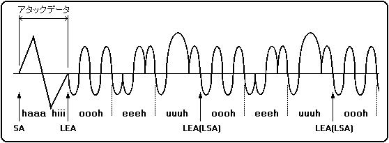
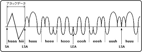
● In the case of normal loop ┌────┬────┬────┬────┬────┬────┬────┬────┬──── 
│ haaa │ hiii │ huu │ heeee │ hoo │ huu │ hee │ hoo │ huu 
└────┴────┴────┴────┴────┴────┴────┴────┴─── 
↑ ↑ ↑ ↑ 
SA LSA LEA (LSA) LEA (LSA)
 
● In case of reverse loop 
┌────┬────┬────┬────┬────┬────┬────┬────┬─── 
│ haaaa │ hiii │ oooh │ eeeh │ uuuh │ oooo │ eeeh │ uuuh │ oooo 
└────┴────┴────┴────┴────┴────┴────┴────┴─── 
↑ ↑ ↑ ↑ 
SA LEA LSA (LEA) LSA (LEA)
 
● For alternative loops 
┌────┬────┬────┬────┬────┬────┬────┬────┬─── 
│ haaaa │ hiii │ huu │ heeee │ hoo │ oooh │ eeee │ uuuh │ huu 
└────┴────┴────┴────┴────┴────┴────┴────┴─── 
↑ ↑ ↑ ↑ 
SA LSA LEA LEA 

Is pronounced.

Furthermore, the waveforms of the normal loop, reverse loop, and alternative loop can be represented as shown in Figure 4.5. Note that the uuuh, eeeh, oooh waveforms are inverted huuu, heee, hooo waveforms.

Figure 4.5 Loop waveform
Define each waveform of "hu", "he", and "ho" as shown in the figure below.

● In the case of normal loop

● In case of reverse loop

● For alternative loops


BackForward
HARDWARE ManualSCSP User's Manual
Copyright SEGA ENTERPRISES, LTD., 1997