Pause songs and sound effects- P1
- Pronunciation control number (0-7)
List ▲ ▼
- ● 03H PAUSE
- Pause songs and sound effects
- P1
- Pronunciation control number (0-7)
List ▲ ▼
- ● 04H PAUSE OFF
- Unpause songs and sound effects
- P1
- Pronunciation control number (0-7)
List ▲ ▼
- ● 05H SEQUENCE VOLUME
- Volume control or fade in / out
- P1
- Pronunciation control number (0-7)
- P2
- Volume (0-255) The larger the value around 128, the louder the volume. Previously, 127 was the default and the volume could only be turned down, but in Ver-2.00 and later it can be louder than when sampled. However, if you set an extremely large value, it may be distorted, so be careful.
- P3
- Fade rate (0-255) Specifies the time to reach the specified sequence volume from the current sequence volume as a rate (0 to 255). The larger the value, the slower the change, 255 is the longest, and 1 is the shortest. (If it is 0, only the sequence volume is set without fading.) Fade is performed from the current sequence volume toward the specified sequence volume. Fade-in or fade-out is determined by whether the specified sequence volume is larger or smaller than the current sequence volume.
List ▲ ▼
- ● 06H STOP ALL
- Stop playing all
- No parameters
List ▲ ▼
- ● 07H TEMPO CHANGE
- Change the tempo of songs and sound effects
- P1
- Pronunciation control number (0-7)
- P2
- dummy (exists to place P3 and P4 at even addresses)
- P3-P4
- Tempo value (+32767-> -32768) The relative tempo value to the standard tempo value (0000h). Every 1000h (4096), the tempo is doubled, and when it is minus, the tempo is halved. In other words, you have 4096 levels of accuracy to control the tempo until it doubles (or halves). Since 0 is the reference tempo, you can always return to the original tempo by specifying 0000h.
List ▲ ▼
- ● 08H MAP CHANGE
- Make a map change
- P1
- Area map number (0-255) A sequential area map number that specifies the number of the area map from the beginning in the sound area map.
There are many scenes in the game, and the area maps are usually different. Therefore, you must specify the area map before playing the sequence. Select the desired area map from the sound area map and change the map. After the map change is completed, the sound data will be transferred according to the map. Now you are ready to play the sequence. Be sure to change the map once after starting the sound driver. After that, it must be done every time the area map changes. Follow steps 1 to 6 below to change the map.
How to change the map
| order | Processing content | explanation |
|---|
| 1 | Stop all pronunciation | Issue the "Sound Initial (10h)" command. In the parameter, specify all sound stop and all initialization. |
| 2 | Switch area map | Issue the "Map Change (08h)" command. In the parameter, specify the number of the area map you want to switch. |
| 3 | Transfer sound data | Transfer sound data from SH address 25A0B000. If you have sound data divided into multiple files, transfer each data according to the area map. |
| Four | Notify transfer completion | Set all the transferred bits of the sound area map CRNT work (from SH address 25A00500h) to "1" for the amount after the transfer is completed. |
| Five | Set DSP | Issue the "Effect Change (83h)" command if necessary. |
| 6 | Set the mixer | Issue the "Mixer Change (87h)" command. Be sure to set the mixer even if you are not using a DSP. |
You can play the sequence at any time after the map change. To play the sequence, issue sound control commands (sequence start, sequence stop, etc.) that control the sequence playback.
Note 1: If you switch the area map or replace the sound data in use while the sound is still sounding, the system may run out of control.
Note 2: Since the DSP work RAM is used for the internal processing of the DSP, the contents of this area are constantly rewritten by the DSP while the DSP is operating. Be careful when changing the area map that changes the size and address of the DSP work RAM. If the DSP is running, the sound data transferred to the location that was used as the DSP work RAM until just before will be destroyed.
List ▲ ▼
- ● 09H DIRECT MIDI CONTROL
- Send MIDI event as a command
- P1
- MIDI command word (00h-FFh)
- P2
- MIDI channel word (00h-FFh)
- P3
- MIDI data 1 (00h-7Fh)
- P4
- MIDI data 2 (00h-7Fh)
Since the sound driver is a sound source that sounds with MIDI messages, you can also make it sound by giving MIDI messages directly without creating sequence data. This command is an interface for that purpose, and has a message block given to the sound driver as a parameter.
The message block is a 4-byte data block with parameters for starting pronunciation added to the MIDI message, and has the structure shown in the figure below. | 7 | 6 | 5 | 4 | 3 | 2 | 1 | 0 |
|---|
| 0 | Priority level | CMD |
|---|
| 1 | KNo | MIDI Ch |
|---|
| 2 | MIDI Data # 1 |
|---|
| 3 | MIDI Data # 2 |
|---|
| Priority level | 0-31 | Pronunciation priority at Sequence Start |
| CMD | 0-7 | MIDI command |
| KNo | 0-7 | Pronunciation control number |
| MIDII Ch | 0-31 | MIDI channel |
| MIDI data # 1 | 0-127 | MIDI data byte # 1 |
| MIDI data # 2 | 0-127 | MIDI data byte # 2 |
Correspondence with the actual MIDI Event
| CMD value | Corresponding MIDI Event |
| 0 | (80h-8Fh) Note Off Event |
| 1 | (90h-9Fh) Note On Event |
| 2 | (A0h-AFh) After Touch |
| 3 | (B0h-BFh) Control Change |
| Four | (C0h-CFh) Program Change |
| Five | (D0h-DFh) Channel Pressure |
| 6 | (E0h-EFh) Pitch Wheel |
| 7 | (F0h-FFh) System Massage |
Issue the "MIDI Direct Control (09h)" command with the 4 bytes of the message block as the parameters P1, P2, P3, P4. However, it has the following advantages and disadvantages, so please consult with the sound creator before selecting a better method.
Strong Points
- Real-time control that cannot be held in advance for sequence data is possible.
- There is no need for data creation work such as sequence creation and compression.
- Since the compression / decompression process can be omitted, no addition is required.
Disadvantages- Instead of being able to do anything, in some cases you have to understand a lot of content before programming. (If you do not know the relationship between the MIDI channel and the corresponding tone, the DSP program and the mixer specifications, etc., you will not be able to use it correctly, so you need to match it with the sound creator.)
List ▲ ▼
- ● 0AH START VOLUME ANALYZER
- Digital Audio In input level analysis started
- No parameters
List ▲ ▼
- ● 0BH STOP VOLUME ANALYZER
- Digital Audio In input level analysis completed
- No parameters
List ▲ ▼
- ● 0CH DSP STOP
- DSP stop and initialization
- No parameters
List ▲ ▼
- ● 0DH ALL NOTE OFF
- Stop all pronunciation
- No parameters
Note: Do not use normally as it is for emergencies.
List ▲ ▼
- ● 0EH SEQUENCE PAN
- Control PANPOT from the game
- P1
- Pronunciation control number (0-7)
- P2
- The 7th bit is the switch. A bit that indicates whether to control the sequence PAN. 0 controls the sequence PAN. If it is 1, no control is performed. Bits 6 to 0 are PAN data values that MIDI can take (0 to 7FH).
Details of MIDI PAN data (correspondence with SCSP PAN)
| MIDI PAN | 0 | 1 | 2 | 3 | Four | Five | 6 | 7 | 8 | 9 | A | B | C | D | E | F |
| 00h --0Fh | 1Fh | 1Fh | 1Fh | 1Fh | 1Eh | 1Eh | 1Eh | 1Eh | 1Dh | 1Dh | 1Dh | 1Dh | 1Ch | 1Ch | 1Ch | 1Ch |
| 10h ―― 1Fh | 1Bh | 1Bh | 1Bh | 1Bh | 1Ah | 1Ah | 1Ah | 1Ah | 19h | 19h | 19h | 19h | 18h | 18h | 18h | 18h |
| 20h --2Fh | 17h | 17h | 17h | 17h | 16h | 16h | 16h | 16h | 15h | 15h | 15h | 15h | 14h | 14h | 14h | 14h |
| 30h --3Fh | 13h | 13h | 13h | 13h | 12h | 12h | 12h | 12h | 11h | 11h | 11h | 11h | 10h | 10h | 10h | 10h |
| 40h-4Fh | 00h | 00h | 00h | 00h | 01h | 01h | 01h | 01h | 02h | 02h | 02h | 02h | 03h | 03h | 03h | 03h |
| 50h-5Fh | 04h | 04h | 04h | 04h | 05h | 05h | 05h | 05h | 06h | 06h | 06h | 06h | 07h | 07h | 07h | 07h |
| 60h-6Fh | 08h | 08h | 08h | 08h | 09h | 09h | 09h | 09h | 0Ah | 0Ah | 0Ah | 0Ah | 0Bh | 0Bh | 0Bh | 0Bh |
| 70h --7Fh | 0Ch | 0Ch | 0Ch | 0Ch | 0Dh | 0Dh | 0Dh | 0Dh | 0Eh | 0Eh | 0Eh | 0Eh | 0Fh | 0Fh | 0Fh | 0Fh |
○ The values in the table are SCSP PAN data (00h-1Fh: 32 steps).
○ Since MIDI PAN data has 128 levels, the lower 2 bits are ignored when converting to SCSP PAN data.
 Left Center Right
 00h ← −−−−−−− → 40h ← −−−−−−− → 7Fh
|
Correspondence table of SCSP PAN and MIDI PAN
| PAN | L (db) | R (db) | Localization | | PAN | L (db) | R (db) | Localization |
| 00h | -00.0 | -00.0 | C | | 10h | -00.0 | -00.0 | C |
| 01h | -03.0 | -00.0 | R1 | | 11h | -00.0 | -03.0 | L1 |
| 02h | -06.0 | -00.0 | R2 | | 12h | -00.0 | -06.0 | L2 |
| 03h | -09.0 | -00.0 | R3 | | 13h | -00.0 | -09.0 | L3 |
| 04h | -12.0 | -00.0 | R4 | | 14h | -00.0 | -12.0 | L4 |
| 05h | -15.0 | -00.0 | R5 | | 15h | -00.0 | -15.0 | L5 |
| 06h | -18.0 | -00.0 | R6 | | 16h | -00.0 | -18.0 | L6 |
| 07h | -21.0 | -00.0 | R7 | | 17h | -00.0 | -21.0 | L7 |
| 08h | -24.0 | -00.0 | R8 | | 18h | -00.0 | -24.0 | L8 |
| 09h | -27.0 | -00.0 | R9 | | 19h | -00.0 | -27.0 | L9 |
| 0Ah | -30.0 | -00.0 | R10 | | 1Ah | -00.0 | -30.0 | L10 |
| 0Bh | -33.0 | -00.0 | R11 | | 1Bh | -00.0 | -33.0 | L11 |
| 0Ch | -36.0 | -00.0 | R12 | | 1Ch | -00.0 | -36.0 | L12 |
| 0Dh | -39.0 | -00.0 | R13 | | 1Dh | -00.0 | -39.0 | L13 |
| 0Eh | -42.0 | -00.0 | R14 | | 1Eh | -00.0 | -42.0 | L14 |
| 0Fh | --∞ | -00.0 | R15 | | 1Fh | -00.0 | --∞ | L15 |
List ▲ ▼
- ● 10H SOUND INITIALIZE
- Initialize the sound driver
- P1
- Stop playing all sequences (0-1)
- P2
- Stop playing all PCM streams (0-1)
- P3
- Stop playing CD-DA (0-1)
- P4
- DSP initialization (0-1)
- P5
- Mixer initialization (0-1)
* P1 to P5 are all 01h for execution instructions. At 00h, nothing is done. The values of P1 to P5 of the sound initial (10h) command execute the corresponding processing when it is 01H, and are ignored when it is any other value. This command is mainly intended to be set just before issuing a MAP change.
Details of P1 to P5
- According to the execution instruction (01h) of P1, the stop is executed for all the sequences currently being sounded. This does not affect other sounds (PCM stream playback, CD-DA playback).
- According to the execution instruction (01h) of P2, the stop is executed for all the PCM stream playback currently being sounded. This does not affect other sounds (sequence playback, CD-DA playback).
- According to the execution instruction (01h) of P3, the output is turned off by setting the direct components [EFSDL] and [EFPAN] of the CD-DA input components [EXTS0] and [EXTS1] to "00H". increase. Therefore, if the CD-DA input is processed and output by the effect, the volume will not be turned off. This does not affect other sounds (sequence playback, PCM stream playback).
| Sound address | 100217H.b ← 00H |
| 100237H.b ← 00H |
- The DSP section with built-in sound source is initialized according to the execution instruction (01h) on P4. Actually, the following data is set in the DSP register to turn off the output of the effect component and prohibit the DSP from accessing (R / W) the D-RAM. At this time, the mixer is also initialized, but it is restored. This has no effect on other sounds (sequence playback, CD-DA playback, and PCM stream direct components).
| [IMXL] | ← 00H |
| [EFSDL], [EFPAN] | ← 00H |
| [MPRO] | ← 00000000H |
| [COEF] | ← 000H |
| [TEMP] | ← 000000H |
- According to the execution instruction (01h) of P5, [EFSDL] = [EFPAN] = 0 is written to all [EFREG] in the mixer section, and the effect component is not output. This has no effect on other sounds (sequence playback, CD-DA playback, and PCM stream direct components).
List ▲ ▼
- ● 11H YAMAHA 3D CONTROL
- YAMAHA 3D sound control
- P1
- Distance (0-127) The distance from the listening point to the virtual sound source of the YAMAHA 3D sound.
The value is 0 and the distance is 0. The larger the value, the greater the distance. - P2
- Direction (0-127) The direction of the virtual sound source of the YAMAHA 3D sound as seen from the listening point.
A value of 0 is 0 degrees to the right, 32 is 90 degrees to the right, 64 is 180 degrees to the right, and 96 is 270 degrees to the right. - P3
- Height (0-127) The height of the virtual sound source of the YAMAHA 3D sound as seen from the listening point.
A value of 0 is directly below, 32 is eye height, 64 is directly above, and 96 is rear eye height.
List ▲ ▼
- ● 12H QSOUND CONTROL
- Qsound control
- P1
- Channel number (0-7) Q The number of the channel that controls the sound.
Since there are a maximum of 8 channels, specify 0 to 7. - P2
- PAN Position (0-30) Q Specifies the PAN position of the sound. 0 is 90 degrees to the left, 15 is the center, and 30 is 90 degrees to the right.
List ▲ ▼
- ● 13H YAMAHA 3D INITIALIZE
- YAMAHA 3D, Qsound Localization initialization
- No parameters
List ▲ ▼
- ● 14H TEMPO MODE
- P1
- Tempo mode (0 / plus / minus) If the tempo is changed during sequence playback, the original tempo will be restored during the sequence loop. In this version, we have prepared some tempo modes to avoid it.
- 0: Normal mode
- Performs tempo processing as before.
- 1-127: Ignore mode
- Ignore tempo changes during the sequence. Tempo control is possible only with the host command.
- 128 --255: Relative tempo mode
- All tempo changes during the sequence will work. The host side sets the relative value to it with the TEMPO RATIO command. It is just like shifting the tempo change due to the sequence with the TEMPO RATIO command.
List ▲ ▼
- ● 15H TEMPO RATIO
- Relative tempo value setting
- P1-P2
- Relative tempo value (+32767-> -32768) Relative tempo value to the standard tempo value (0000h). Every 1000h (4096), the tempo is doubled, and when it is minus, the tempo is halved. In other words, you have 4096 levels of accuracy to control the tempo until it doubles (or halves). Since 0 is the reference tempo, you can always return to the original tempo by specifying 0000h.
List ▲ ▼
- ● 80H CD-DA LEVEL
- Adjust CD-DA level
- P1
- CD-DA Level Left 8 levels (00h-E0h) CD-DA output level setting. There are 8 levels of minimum volume (= Off) at 00h and maximum volume at E0h.
 Off ← −−−−−−−−− → Max
00h, 20h, 40h, 60h, 80h, A0h, C0h, E0h |
- P2
- CD-DA Level Right 8 levels (00h-E0h) CD-DA output PAN setting.
Details of 8 steps: (off) 00h, 20h, 40h, 60h, 80h, A0h, C0h, E0h (MAX)
CD-DA playback is a method of directly outputting the audio data of the audio track of a CD in hardware. This is the same as the principle of a tape recorder, and the recorded sound is played back as it is. The audio data read from the CD is automatically flowed into the SCSP, so all you have to do is set the CD-DA level of the SCSP and the audio output will start.
CD-DA flow
Playback of the CD-DA is performed by reading the audio data from the CD drive and setting the audio output from the SCSP.
To read audio data, use the "CDC library" of the system library. Audio data can be read by calling the following two functions. For more information on the CDC library, refer to the CDC library user's manual. Use the "CD-DA Level (80h)" and "CD-DA Pan (81h)" sound control commands to set the audio output from the SCSP. Audio data is transferred directly from the CD interface to the SCSP and output as audio. Therefore, the main system only makes a playback request to the CD interface, and there is no need to read data or transfer it to sound memory. This is the least burdensome playback method for the main system and sound system, but it occupies the CD continuously during playback. In other words, you will not be able to access the CD other than making sound. However, if that is allowed, it will be possible to achieve the maximum quality of this sound system.
The frequency and data width are fixed at 44.1KHz, 16bit, which is equivalent to the CD standard, and the pitch and tempo cannot be changed during playback. At the same time, a very large amount of audio data is required to achieve this quality, so one CD can only contain about 10 to 20 songs, as is the case with ordinary music CDs. Actually, game programs and image data are included, so only about 5-6 songs can be included.
The CD-DA data is the PCM audio waveform data itself. Therefore, the CD-DA data has the recorded PCM waveform data as it is as a data file. It's very large data, but it's the simplest audio data that doesn't require any processing or work.
CD-DA data can be created with the waveform editor of the sound tool provided by SEGA or a commercially available waveform editing tool. Any tool can be used as long as it can output 16-bit stereo PCM data at 44.1KHz. There are two methods, one is to directly digitally record songs and sound effects, and the other is to convert analog voice to digital. In the case of monaural, the same data will be entered in Lch and Rch.
CD-DA data format| Data 1 | Lch low (8bit) |
|---|
Lch high (8bit) |
Rch low (8bit) |
Rch high (8bit) |
| Data 2 | Lch low (8bit) |
|---|
Lch high (8bit) |
Rch low (8bit) |
Rch high (8bit) |
 ::
 ::
 ::
 ::
:: | ::
::
::
::
:: |
|---|
| Data n | Lch low (8bit) |
|---|
Lch high (8bit) |
Rch low (8bit) |
Rch high (8bit) |
Note 1: The 16-bit Low / High relationship of the PCM waveform data output by various tools may be reversed depending on the tool. Generally, it is Low / High for Intel CPUs and High / Low for Motorola formats, so convert to Intel formats for Motorola formats. It is convenient to have a tool that reverses the data Low / High if necessary. Note 2: When using DSP (effect) for CD-DA, it is necessary to set the mixer. When using DSP, prepare the necessary mixer data and issue the "Mixer Change (87h)" command. Even if there is no sequence playback, tone data for mixer settings is required.
List ▲ ▼
- ● 81H CD-DA PAN
- CD-DA output Panpot settings
- P1
- CD-DA PAN Left 32 steps (0-31)
- P2
- CD-DA PAN Right 32 steps (0-31)
List ▲ ▼
- ● 82H TOTAL VOLUME
- Total volume setting
- P1
- Total Volume 16 levels (0-15) SCSP total volume (overall volume for all playback) settings. 0 is the lowest volume (= Off), and 15 is the highest volume in 16 steps.
List ▲ ▼
- ● 83H EFFECT CHANGE
- Switching effects
- P1
- Effect bank number (0-15) Specifies the number of DSP bank from the beginning when there are multiple DSP banks (DSP microprogram storage areas) in the current area map. One area map can have up to 16 DSP banks, so it can be a value from 0 to 15. 0 whenever there is only one DSP bank.
List ▲ ▼
- ● 85H START PCM STREAM
- PCM stream playback started
- P1
- bit7
0: mono 1: stereo - bit6-5
unused - bit4
0: 16bitPCM 1: 8bitPCM - bit3-0
Start playback PCM stream playback number (0-7) Since PCM stream playback can play up to 8 streams at the same time, specify the playback number of the PCM stream from 0 to 7. Note that in stereo, one playback number plays two streams, Lch / Rch. The total of monaural and stereo is up to 8 streams, so if you exceed 8 streams, the command will be ignored. - P2
- bit7-5
Direct sound output level 8 levels (0-7) Direct sound output level setting. 0 is the lowest volume (= Off), and 7 is the highest volume. - bit4-0
Direct sound output PAN 32 steps (0-31) Direct sound output PAN setting. See the SEQUENC PAN section on page 13 for more information. - P3-P4
- PCM stream buffer start address (0000h-FFFFh) The start address of the PCM stream buffer. Specify the upper 16 bits of the 20-bit address.
- P5-P6
- PCM stream buffer size (0000h-FFFFh) The size of the PCM stream buffer. Since it is the number of samples for 1ch, the same value can be entered at MONO, STEREO, 16bit, or 8bit.
- P7-P8
- pitch word (0000h-7FFFh) Specify the value (16 bits) of the pitch register of SCSP as it is.
Pitch Word (16bit) configuration 15 | 14 | 13 | 12 | 11 | Ten | 9 | 8 | 7 | 6 | 5 | 4 | 3 | 2 | 1 | 0 |
|---|
| 0 | OCT | 0 | FNS |
OCT: Specifies the octave as a two's complement. You can specify from -8 octaves to +7 octaves.
FNS: Specify the range from the reference pitch (0) to one octave above (1023) in 1024 steps.
Bits 15 and 10 are always 0. - P9
- bit7-3
Effect input channel (0-15) [P9 = Rch] DSP 16ch Effect In selection. Since there are 16 channels of DSP effect input, specify 0 to 15. Please refer to the section "Chapter 6 Supplementary Explanation 6-7 DSP and Mixer" for a detailed explanation. - bit2-0
Effect input level 8 levels (0-7) Specify the level of the direct sound sent to the effect input channel from 0 to 7. 0 is the lowest level (= Off), 7 is the highest level, 8 levels. - P10
- bit7-3
Effect input channel (0-15) [P10 = Lch] - bit2-0
Effect input level 8 levels (0-7) - P11
- Total level 256 steps (max: 00h-FFh: min) The total level of the slots used for stream playback. You can adjust the volume finer than the direct sound output level.
PCM stream playback is a method of playing back long PCM waveform data by continuously performing the process of writing the next waveform data to the part where playback has ended while looping back the PCM waveform data. You can play long PCM waveform data such as speaking voice, long sound effects, and recorded BGM that does not fit in the sound memory. Since you can know which part of the waveform data is currently being played, write the next waveform data to the part where playback has finished. In the case shown in the figure below, while the waveform data A has finished playing and the waveform data B is playing, the next waveform data is written to the part of the waveform data A. By repeating this process, any long waveform data can be played back continuously.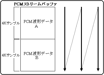
A, B, A, B, A, B ..... and continuous loop playback
Follow the procedure below to play the PCM stream. Also, in stereo, it is necessary to perform the following processing for two channels, the left channel and the right channel.| order | process |
|---|
| 1 | Transfer the first waveform data to the area of waveform data A and waveform data B. |
| 2 | Issue the sound control command "PCM start (85h)". |
| 3 | When the playback of waveform data A is completed, the next waveform data is transferred to the area of waveform data A. |
| Four | When the playback of waveform data B is completed, the next waveform data is transferred to the area of waveform data B. |
| Five | Repeat steps 3 and 4 above |
| 6 | When finished, issue the sound control command "PCM stop (86h)". |
Note: The size of the buffer, transfer method, transfer timing, etc. are free for the main system, so select the most suitable method according to the situation without being bound by the above procedure.
How to hold the data area
In order to play PCM stream, a data area (PCM stream buffer) for playing PCM waveform data is required. The PCM stream buffer can be anywhere on the sound memory. Normally, unused parts of tone data, song data, etc. are used, but if there is a tone bank that is not used at the same time as PCM stream playback, that area can also be used.
The current playback position can be known in 4K sample units. Therefore, PCM stream playback can be performed by having at least two 4K sample buffers. The size of the PCM stream buffer can be set up to 64K samples per channel, so it can be set freely within this range. Buffer rewrite timing
When PCM stream playback starts, the current waveform playback position is written to the host interface work. The playback position is a numerical value from 0 to 15, the value is 0 at the start of playback, and it counts up by 1 each time 4K sample playback progresses. When playback is completed to the end of the buffer, playback is repeated from the beginning of the buffer, so the value of the playback position returns to 0 at this point.| Example of how to hold a buffer | Playback position value |
| If you have two 4K sample buffers | 0, 1, 0, 1, 0, 1 ... |
| If you have 3 buffers of 4K sample | 0, 1, 2, 0, 1, 2, 0, 1, 2 ... |
| If you have 16 buffers of 4K sample | 0, 1, 2, 3 ---- ---- 12, 13, 14, 15, 0, 1, 2, 3 ... |
The main system should monitor this playback position and transfer the next waveform data. Since the PCM stream buffer can take up to 64K samples, you can select from a minimum of 2 screens to a maximum of 16 screens.
It is also possible to generate an interrupt to the main system when the playback position is updated, so use this if necessary. Since the control information of this interrupt is included in the system interface work, refer to the section "7 System interface work" for the setting contents.
Load during transfer
Since the PCM playback slot is fixed at 44.1KHz in terms of hardware, one sample is played every 22.68usec from the start of playback. In other words, after the start of playback, it is necessary to continue to supply waveform data for 44,100 samples per second per channel. It is 44,100 bytes for 8-bit PCM and 88,200 bytes for 16-bit PCM.
The time required for this transfer, including reading from a CD and transferring to sound memory, is the load on the main system. Since the transfer time depends on the hardware of the main system, it can be calculated by the CD rotation wait, seek time, SH (or DMA) transfer clock and the number of transfer bytes.
However, since the above number of bytes is the amount of data at 44.1KHz, for example, if half of 22KHz is sufficient, the amount of data will be half that amount, and the transfer load will also be halved. Conversely, when playing stereo or playing multiple channels at the same time, the load will be heavier. Stereo playback
PCM stream playback can be performed in stereo. Note that stereo playback uses twice as much memory as monaural as shown below. Since the buffer size specified by the command parameter for starting playback is the number of samples for one channel, actually prepare an area twice that.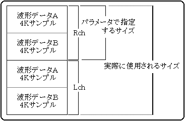
Support for playback frequencies other than 44.1KHz
Since SCSP always reproduces waveform data at a frequency of 44.1KHz, pitch parameters can be used to reproduce waveform data at frequencies other than this. For example, if you play a half 22KHz one, it will be played at twice the pitch as it is, so if you play it at half the playback pitch, it will be played at the original pitch. The pitch is in the range of ± 8 octaves (OCT), and one octave can be further divided into 1024 steps (FNS), so it can handle any frequency within this accuracy range, but in reality it is. Anomalous settings are not made, so they are described in the correspondence table.
| Sampling rate | OCT | FNS | Set value |
| 44.1kHz | 00 | 0000 | 0000 |
| 32kHz | 0F | 01CE | 79CE |
| 22kHz | 0F | 0000 | 7800 |
| 16kHz | 0E | 01CE | 71CE |
| 11kHz | 0E | 0000 | 7000 |
| 8kHz | 0D | 01CE | 69CE |
| 5.5kHz | 0D | 0000 | 6800 |
| 4kHz | 0C | 01CE | 61CE |
- Precautions for continuous transfer
When transferring waveform data, avoid long-term continuous transfer so that the sound CPU can operate. Please note that this is prioritized and the sound CPU cannot operate while the main system is accessing the sound memory. If continuous transfer is required, divide it into transfers of up to 1 msec. The sound CPU can be operated by leaving a gap.
- Precautions when using DSP
When using DSP (effect) for PCM stream playback, it is necessary to set the mixer. When using a DSP, prepare the necessary mixer data and issue a mixer setting command. Even if there is no sequence playback, tone data for mixer settings is required.
Remarks: One sample is the minimum unit data of PCM waveform data, and its size depends on the data width. 1 byte for 8 bits and 2 bytes for 16 bits. Therefore, in the case of a 4K sample, it is 4096 bytes for 8-bit PCM and 8192 bytes for 16-bit PCM. Up to 8 PCM stream playbacks are functionally possible, but in reality it is impossible due to processing power. Since stream playback does not run on the sound CPU alone, we recommend that you repeat experiments from the early stages of development in consideration of the processing speed of the game. Be especially careful in games where SH2 is overused for polygon calculations, as it can cause frame over.
List ▲ ▼
- ● 86H STOP PCM STREAM
- PCM stream playback stop
- P1
- Stop playback PCM stream playback number (0-7)
List ▲ ▼
- ● 87H MIXER CHANGE
- Mixer switching
- P1
- Tone data bank number (0-15) This is a number to distinguish when there are multiple tone banks (storage areas for tone data) in the current area map. Since one area map can have up to 16 tone banks, it can be a value from 0 to 15. (See 5-1-4 Sound Area Map CRNT Work Map Information).
- P2
- Mixer number in tone data (0-127) Since multiple mixer data can be stored in one tone data, specify the number of mixer data from the beginning in the tone data. A maximum of 128 mixers can be stored in one tone data, so it can be a value from 0 to 127. 0 whenever there is only one mixer data.
What is a mixer
The mixer is hardware for balancing the volume of the SCSP sound source and the localization (distribution to the left and right). There are only two types of sound sources, a sound source slot and a digital audio input, but since each can pass through a DSP, the mixer can be divided into the following four types of mixer blocks. Mixer configuration
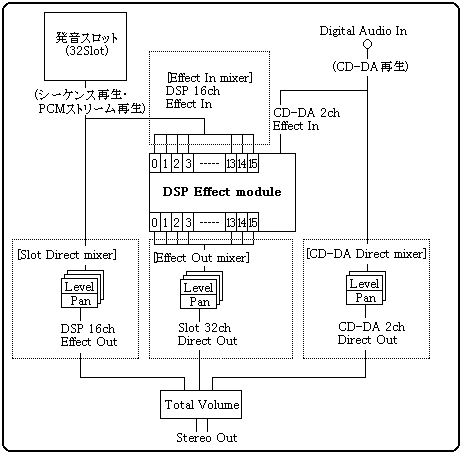
- Slot Direct mixer
- : Direct (not through DSP) output level from the sounding slot and PAN
- CD-DA Direct mixer
- : Direct (not through DSP) output level from CD-DA and PAN
- Effect In mixer
- : Input level to DSP
- Effect Out mixer
- : Effect level from DSP (through DSP) and PAN
Of these, "Slot Direct Mixer" and "Effect In Mixer" have already been set in the tone data, so no special control is required. For the "CD-DA Direct mixer", the dedicated "CD-DA Level (80h)" and "CD-DA Pan (81h)" commands are available for control.
Therefore, the term "mixer" in this manual specifically means the above "Effect Out mixer". The mixer referred to in this manual is "16ch effect level and PAN settings output from the DSP".
DSP and mixer
The mixer is the setting for the sound outlet from the DSP. Therefore, even if the effect processing works normally and the effect is applied correctly, the effect sound will not be output unless the correct mixer is set. The mixer is the data that sets the volume and localization for 16 channels of the DSP output channel, and is created by the sound creator as part of the tone color data. In addition, since all the sounds of sequence playback, PCM stream playback, and CD-DA playback are input to the DSP, it is possible to correctly grasp which sound enters which channel and exits from which channel in which scene. Must be controlled above. Before switching effects, check which mixer is compatible and what the mixer specifications are.
If you use MIDI control change to set the mixer, you cannot select the bank. This is because due to the MIDI format, it is not possible to send two arguments, bank and mixer number, at the same time. Therefore, only the mixer number will be sent, but the bank at that time will be sent to the bank selected by the bank change.
List ▲ ▼
- ● 88H MIXER PARAMETER CHANGE
- Switching mixer parameters
- P1
- Effect output channel (0-17) DSP 16ch Effect Out selection. Since there are 16 channels of DSP effect output, specify 0 to 15. Also, when selecting CD-DA, specify 16 (Lch) or 17 (Rch) specially.
- P2
- bit7-5
Effect output level 8 levels (0-7) Specify the level of the effect sound output from the effect output channel from 0 to 7. 0 is the lowest level (= Off), 7 is the highest level, 8 levels. - bit4-0
Effect output PAN 32 steps (0-31) Specify the PAN of the effect sound output from the effect output channel from 0 to 31. For details, refer to the section "Chapter 7 Appendix 7-2 Details of SCSP PAN (32 steps)".
List ▲ ▼
- ● 89H HARDWARE CHECK
- Hardware check
- P1
- Check item
- 00h: DRAM 4Mbit read / write
- 01h: DRAM 8Mbit read / write
- 02h: SCSP MIDI
- 03h: Sound source output (L / R)
- 04h: Sound source output (L)
- 05h: Sound source output (R)
The following is the details of the check contents performed by the hard check (89h) command. At the time of checking, a value from 0 to 5 is specified in the command parameter P1, and the following check is performed according to that value. The following values are stored in the system interface table (address 418h: word) for all the check results.
7FFFH: Memory check Error
8000H: Memory check Ok
| 00h | Executes read / write check of D-RAM (4M bits) for sound. At this time, please note that the DSP is initialized to prohibit internal memory access.
The check writes & reads & compares all bits low / high and the result is stored in the system interface table. |
| 01h | Executes read / write check of D-RAM (8M bits) for sound. Others are as described above. |
| 02h | Executes the operation check of MIDI with built-in SCSP. At this time, short-circuit the external MIDI input / output terminals. The result of the check is as described above. |
| 03h | A square wave is output from the LR. At this time, note that slot 025B00000H of SCSP is forcibly used. Also, this sound is automatically turned off in a few seconds. No Map data, song data, or tone data is required to issue this command. |
| 04h | The square wave is output only from the L side. Others are as described above. |
| 05h | Value of P1 |
List ▲ ▼
- ● 8AH PCM PARAMETER CHANGE
- Parameter switching for the PCM stream being played
- P1
- PCM stream playback number (0-7)
- P2
- bit7-5
Direct sound output level 8 levels (0-7) - bit4-0
Direct sound output PAN 32 steps (0-31) - P3-P4
- pitch word (0000h-FFFFh)
- P5
- bit7-3
Effect input channel (0-15) [P5 = Rch] - bit2-0
Effect input level 8 levels (0-7) - P6
- bit7-3
Effect input channel (0-15) [P6 = Lch] - bit2-0
Effect input level 8 levels (0-7) - P7
- Total level 256 steps (max: 00h-FFh: min)
List ▲ ▼
- ● 8BH PCM SLOT ALLOCATION
- Reserve a slot for the PCM stream
- P1
- PCM stream playback number (0-7)
The PCM stream uses a fixed slot, but that slot may be used during sequence playback, and when the PCM stream is started, part of the sequence will be forcibly turned off. If you reserve a PCM slot in advance with this command, the above problem will be solved.
List ▲ ■
- ● 8CH PCM SLOT RELEASE
- Release slots for PCM streams
- P1
- PCM stream playback number (0-7)
Release the reserved slots so that they can be used for sequence playback.
▲ Back | Forward ▼
 ★ SOUND Manual ★ Sound Driver Programmer's Guide
Copyright SEGA ENTERPRISES, LTD., 1997