 ★ Graphic Tools Guide ★ 3D Editor User's Manual
▲ Back | Forward ▼
3D Editor User's Manual / 2. How to use
■ Texture menu
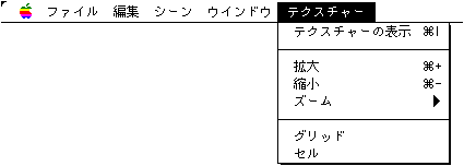
● Texture display
- Opens a texture window that displays texture image files (PICT, DGT, RGB).
● Expansion
- Enlarges the image in the texture window.
● Reduction
- Reduces the image in the texture window.
● Zoom
- It is displayed with the specified zoom by the hierarchical menu.
● Grid
- A grid is displayed for each dot when the display is enlarged by 4 times or more.
● Cell
- A grid is displayed for each cell (8 dots).
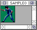
● Tool palette & scene window
- The 3D stereoscopic image is displayed in the following scene window.
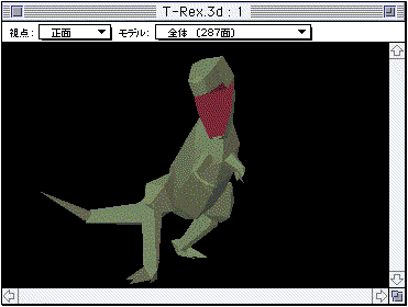
- Move up / down / left / right, move back / forth / left / right, rotate Y-axis, rotate X-axis, rotate Z-axis, enlarge / reduce, select polygons, and combine triangles by dragging the mouse on the scene window after selecting each tool on the tool palette. ..
In addition, the scene window has a menu for specifying the line-of-sight direction and a menu for displaying in model units.- It is possible to select multiple polygons by performing shift + click while using the polygon selection tool. This makes it possible to add material information to multiple selected polygons at once.
- The Triangle Join Tool is a tool that joins two adjacent triangles as shown in the figure below.
First, move the mouse to the first triangle, hold down the mouse button and drag on the adjacent polygons, and when the mouse moves onto the second polygon that can be combined, the two polygons will move. A selection mark is displayed at the same time.
However, such polygons cannot be selected because they cannot be combined if they are not on the same plane.
By holding down the Option key and performing the above operation, polygons that are not on the same plane can be forcibly connected, and data can be saved by taking advantage of the characteristics of quadrilateral polygons.
However, in this case, the information as an accurate solid will be lost, so be careful.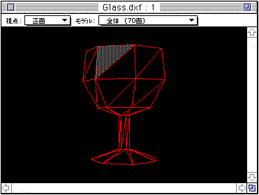
- Also, if the selected polygon is a triangle, the overlapping vertices are displayed by pressing the Option key + Command () keys at the same time.
● Coordinate setting window
- When you select a polygon by pressing the ctrl key + click in the scene window, the coordinate setting window is displayed and you can change the vertex data ((fine adjustment)).
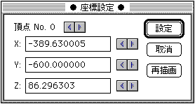
- As for the vertices, the nearest point of the polygon specified by pressing the ctrl key + click is selected, but you can arbitrarily select the vertices on the same polygon on the coordinate setting window. The coordinates can be changed directly by entering a numerical value or according to the movement rate of the vertices in the preferences.
The changed vertex coordinate data is confirmed when the setting button or another vertex is selected, and the setting is canceled with the cancel button. If you want to check the status temporarily during the change operation, click the redraw button. ● Material setting window
- Material settings are made in the scene window below.
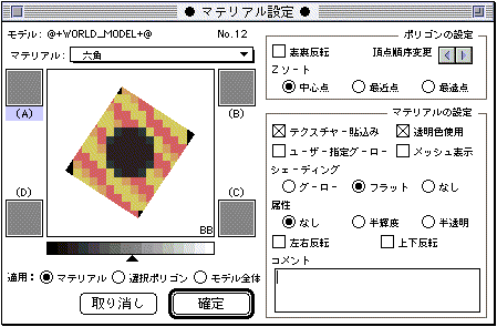
- The polygon selected by the polygon selection tool in the scene window is displayed in the rectangle, and the model name to which this polygon belongs and the polygon number are displayed.
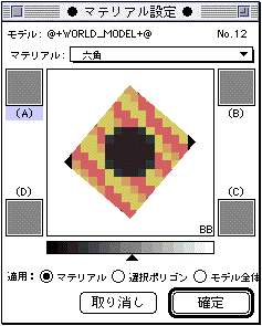
- The window zoom box allows you to make the window smaller as shown below.
- Materials are managed by name. The material set for each polygon is set in the material popup menu.
If you change the material content, it will be reflected in all the polygons that set the material. Each polygon can be switched to any material stored in the file via the Material pop-up menu. You can also add new materials and rename them in this pop-up menu.- Material settings only affect polygons by clicking the confirm button. At this time, the range of influence changes depending on the item specified in "Apply".
- If you click the mouse in the rectangle where the polygon is displayed, you can set the non-texture color of the polygon by the color selector dialog below.
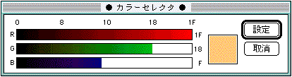
- You can set the gourd color of polygons in the rectangles indicated by (A), (B), (C), and (D) using the same color selector dialog.
However, this color is used only when the "Use user-specified gourd" checkbox is checked.- The level control shown in gray level is the gourd offset.
On "3D Editor", the color calculation result of the polygon is output based on the above-mentioned Goro color and the offset value set here.- * Goo offset setting does not exist as a function of Sega Saturn. Please note that if you want to use the value set here, you need to take action at the program level on the actual machine.
- Each setting included in the polygon setting is an item set for each polygon. The contents set here can be changed in polygon units regardless of the material settings.
"Change Vertex Order" allows you to change the order of polygon vertices. This function is mainly effective when the texture data cannot be set in the desired direction.
If you put a cross in the "Use transparent color" checkbox in the material settings, the black ($ 0000) part of the texture data will be displayed transparently.
▲ Back | Forward ▼
★ Graphic Tools Guide ★ 3D Editor User's Manual
Copyright SEGA ENTERPRISES, LTD., 1997