Describes the specific restrictions of SEGA within this standard. It also describes what you need to do to develop your application.
■ Area division in the disk and arrangement of each area
- Lead-in area
- Program area
- Lead-out area
Figure 2.1 Arrangement of each area on the disk 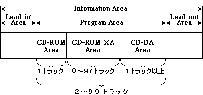
 | Only one track is required for the CD-ROM area (Mode 1). The CD-DA area requires at least one track. |
■ Program Area track layout
Therefore, the program area is divided and arranged in the following order.
- CD-ROM area (Mode 1 track)
- CD-ROM XA area (Mode2 Form1 & Form2 tracks)
- CD-DA area
Also, even if this disc is set in a CD-ROM drive that supports only Mode 1 tracks, the Mode 1 tracks will be placed at the beginning so that there will be no trouble. Therefore, each track must be placed in the above order.
Do not place the CD-ROM tracks and CD-DA tracks alternately, or place the CD-ROM area and CD-DA area in reverse.
The track number in the CD-ROM XA area can be set continuously from "02" to "98".
The track number of the CD-DA area should be set continuously from "02" if there is no CD-ROM XA area, and from the next consecutive track number to "99" if there is a CD-ROM XA area. I can.
Do not place them discontinuously.
Make sure that one track is at least 4 seconds.
 | One track always requires 4 seconds or more, excluding the pause area, pre-gap area, and post-gap area. |
ABS TIME | LSN | FAD | |
First frame | 00:00:00 | − | 0 |
First sector | 00:02:00 | 0 | 150 |
Last sector | 63:01:74 | 283499 | 283649 |
Final frame | 63:03:74 | − | 283799 |
Lead-out area start time | 63:04:00 |
Figure 2.2 Track image when the data track is maximized
(When the audio track is minimized)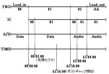
Every minute of audio track usage consumes 9MB of data sectors.
■ Key to specify the position on the disk
To clarify the meaning of the frame address etc., Figure 2.4 shows the relationship between the track structure and the access key.
Figure 2.3 General GAME-CD structure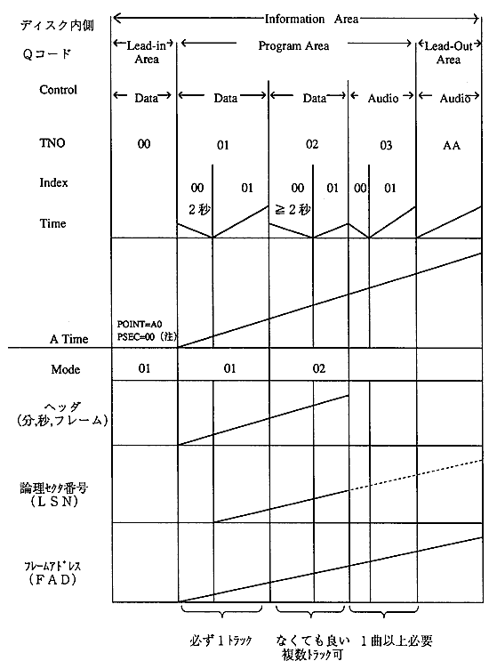
■ Sector structure
GAME-CD uses three types of sectors: Mode1, Mode2 Form1 and Mode2 Form2.
Figure 2.4 CD-ROM and CD-ROM XA sector format 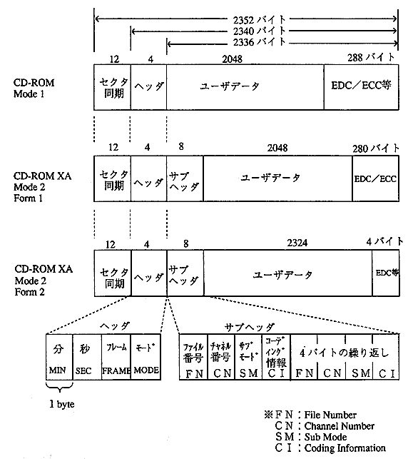
 | Mode2 format without form specification cannot be used. |
■ Header field
There may be an error between the ATIME value of the subcode Q channel and the sector address in the header. Therefore, when identifying the sector, use the header value instead of the subcode Q channel.
Byte subscript | value |
|---|---|
12 | Minute second frame mode |
■ Subheader field
The file number can be used to select sectors that belong to the same file or to exclude files that are not covered.
Depending on the value of the file number, there are the following restrictions.
File number | explanation |
|---|---|
0 | Used for the following files or areas-Files and directories recorded continuously on disk-Others (pathtable, volume descriptor) |
1-255 | It can be interleaved or continuous (it is not clear if it is interleaved with another file). |
Figure 2.5 Sector interleaving by channel number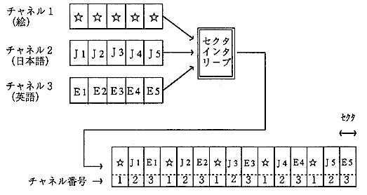
Table 2.3 shows the configuration of submode bytes.
Bit number | Bit name | Default value |
|---|---|---|
7 | End Of File (EOF) | 0 |
- End Of File (EOF):
Only the last sector of the file is set to 1.
Other sectors are 0. - Real Time Sector (RT):
When this bit is 1, the CD-ROM XA must be processed in real time without interruption. - Form (F):
When it is 0, it indicates that it is recorded in Form1, and when it is 1, it indicates that it is recorded in Form2. - Trigger (T):
This bit is used for synchronization in applications with diverse coding information. - Data (D):
This bit is set to 1 for the data sector related to the program.
When this bit is 1, the Form bit must be 0. - Audio (A):
1 is set for the audio sector.
When this bit is 1, the Form bit is also set to 1. - Video (V):
1 is set for the video sector. - End Of Record (EOR):
1 is set at the last sector of the logical record.
The empty sector is required to be a Form2 sector with all 0 user data areas.
 ★ PROGRAMMER'S GUIDE ★ DISC format standard specifications