- The characteristics and logical structure of the CD block as seen from the host are shown below.
- (1) Data format
- The CD buffer manages streams on a fixed-length (2352 bytes) sector, regardless of device.
However, for input / output to and from the device, the effective data length in one sector does not always match 2352 bytes. For hosts, variable length settings from 2048 to 2352 bytes are possible. - (2) Stream selection circuit
- The function of separating and storing streams is realized by a mechanism called aperture and buffer partition. These functions are regarded as logical elements (selectors). By combining selectors, you can build a circuit that selects the required stream.
- (3) Device
- Think of CDs, MPEG, etc. as logical devices that generate and absorb streams. Control the stream flow by connecting a device to the stream selection circuit.
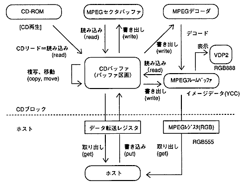
5.1 Data flow
- The overall data flow for the CD block is shown in Figure 5.1.
Figure 5.1 Data flow for the entire CD block
5.2 Stream processing mechanism
- Figure 5.2 shows the overall configuration of the CD block, focusing on the stream flow.
Figure 5.2 Overall configuration of the CD block
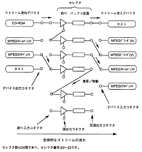
- [Description of each part]
- Device: Generates and absorbs streams. (Stream outflow / inflow device)
- Selector: Consists of aperture and buffer partition to select a stream.
- Aperture: Streams are separated according to the set conditions. (Matches / does not meet the conditions)
- Buffer partition: Stores a stream and releases / erases data at the request of the outside.
- Each device and selector has a connector for connecting. The input / output connectors of the device and selector are connected one-to-one. You can also connect between selectors.
- Connections between connectors that do not pass through the partition allow the stream to flow steadily. It will stop when you enter the lot. The sectors output from the unconnected output connector will be erased.
- Devices are always connected through a selector. The device output connector can only be connected to the aperture input connector, and the device input connector can only be connected to the partition output connector.
5.3 Selector structure
- The processing function of the selector does not depend on the selector or device to which it is connected. All you have to do is separate and store the input stream and output it as requested.
The structure of the selector is shown in Figure 5.3. Figure 5.3 Selector structure (initial state)
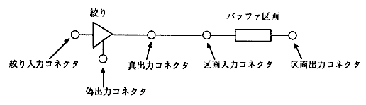
- The initial state of the selector is that the apertures and compartments with the same number are connected through the true output connector and the compartment input connector. Other connectors are not connected.
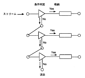
5.3.1 Aperture
- For the aperture, set the conditions of the sector to be passed (FAD range, subheader). The sectors that match the conditions are output to the true output connector and stored in the buffer partition to which they are connected. Other sectors are output to the fake output connector.
The fake output connector can be connected to other aperture input connectors, and the same selection process is performed one after another.
The sectors output from the unconnected output connector will be erased. Figure 5.4 Schematic diagram of stream selection processing
5.3.2 Buffer partition
- (1) Structure of buffer partition
- The CD buffer is divided into multiple buffer partitions. The structure of the buffer partition is shown in Figure 5.5.
Figure 5.5 Buffer partition structure
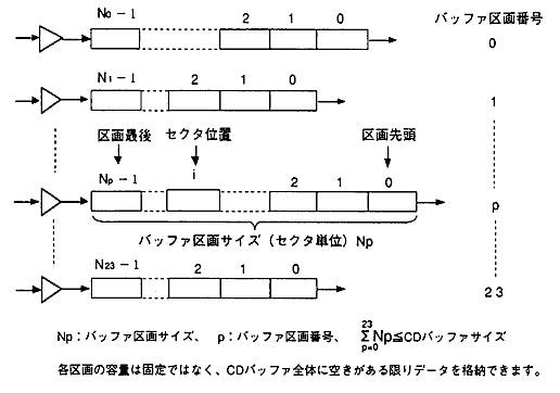
- (2) Storage of sectors in the buffer partition
- The sectors that enter the partition are stored at the end of the partition. The last sector position of the partition is equal to the buffer partition size -1. After storage, the buffer partition size is incremented by 1.
- (3) Emitting and erasing sectors from the buffer partition
- There are two ways to emit a sector from a partition, either leaving the sector in the source partition or erasing it. (You can also instruct only to erase.)
For example, fetching to the host corresponds to "fetching" and "erasing", and inflow and outflow between selectors corresponds to "copying" and "moving". - (4) CD 1-sector interrupt and storage location
- A one-sector interrupt (CSCT flag in the interrupt cause register) in a CD read occurs for each sector when the sector is stored (or erased) in the partition. The CD block remembers the storage partition number of the last read sector, and the host can get that value.
If the ECC count is set to multiple times, 1-sector interrupts do not always occur at equal intervals. Multiple sectors may be stored at once for error correction. 5.3.3 Connector
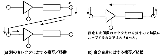
- (1) Connection from buffer partition to aperture (copying / moving sector data)
- Sector data can be copied / moved by connecting the partition output connector to the aperture input connector and flowing sector data. The connection / inflow / outflow process is executed with a single command issuance.
Figure 5.6 Copying / moving sector data
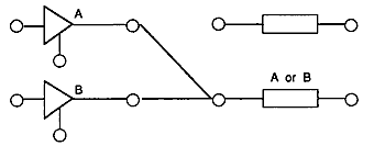
- (2) Selector connection based on OR conditions (many-to-one connection)
- You can connect multiple aperture true output connectors to the same partition input connector. This allows you to store sectors that match any of the multiple conditions. (OR condition: OR condition)
Figure 5.7 Connecting selectors with OR conditions
- (3) Connector type and connection destination
- Table 5.1 Connector types and destinations
Input Output | Aperture input | Parcel input | Device input |
|---|
Device output | ○ | × | × |
True output | × | △ | × |
False output | ○ | × | × |
Partition output | ○ | × | ○ |
- ○: Connectable (1 to 1)… Only one output connector can be connected to one input connector
- Δ: Connectable (many to 1) ... Multiple output connectors can be connected to the same input connector (OR condition)
- ×: Cannot connect
- It depends on each device whether to perform single connection (disconnection) processing with one command or combined processing that combines the connection and inflow / outflow processes.
CD-ROM and MPEG decoder are independent processing, and others (host, copy / move, etc.) are combined processing. 5.3.4 Notes on selectors
- (1) Error in stream processing
- Stream processing generally causes an error when the following operations are performed. (However, no error will occur for CD-ROM devices.)
- When the connection is disconnected by another device while the device is operating
- When the CD buffer is full when reading / writing to the buffer partition
- (2) Selector setting valid timing
- The selector setting becomes effective when the ESEL flag of the interrupt cause register becomes 1 by issuing the selector setting command.
If the selector setting command is issued during CD playback, the FAD for which the setting is valid is within +1 frame (FAD to FAD + 1) with respect to the FAD returned in the CD report. The host should consider the margin and issue the configuration command at least 10 sectors before the target FAD. - (3) Sector data when switching connections
- Even if the connection is switched to another selector when sector data is flowing, such as when reading a CD, no data loss will occur. In other words, data flow is guaranteed during temporary disconnection due to connection switching.
If it is completely separated, the leaked data will be erased. - (4) General access to the buffer partition (general commands that specify the sector position and sector range)
- If you specify an invalid position or range that exceeds the number of data in the partition, the command returns WAIT.
It always returns WAIT if:- When the number of sectors in the partition is 0
- When the specified number of sectors is 0
- Before accessing the partition, be sure to execute Get Number of Sectors of Buffer Partition (CDC_GetSctNum) to make sure that the number of sectors is not 0.
- (5) Erase release from the buffer partition
- In the case of the process of erasing the sector from the partition and releasing it, even if the process is stopped due to an error etc., all the data in the sector range specified first will be erased. (Extracting and erasing sector data, moving, etc.)
5.4 Sector data format
- (1) Basic format
- The sector data format basically conforms to the sector format of CD-ROM XA.
Figure 5.8 CD-ROM XA sector format
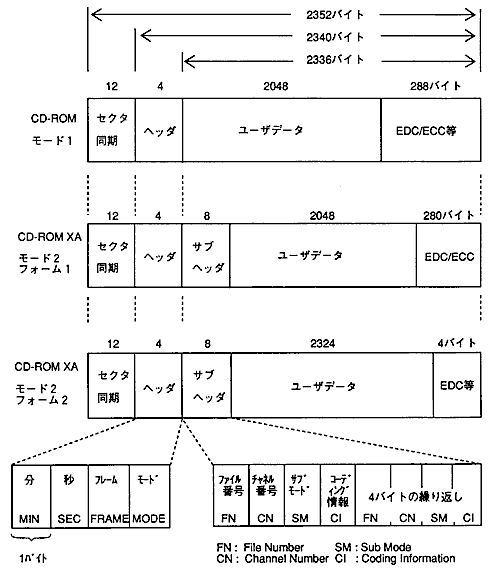
- (2) Handling of subheaders and user data (2048 bytes)
- Subheaders other than mode 2 (the mode part of the header is 02H) are treated as 0.
- Only in mode 1 (mode part of the header is 01H), there is user data immediately after the header. Other than that, it is assumed that the user data is in the same position as Mode 2 Form 1.
- When storing user data in a partition from a device other than a CD-ROM device, treat it in the same way as Mode 2 Form 1. The first 24 bytes are 0, and the end of the user data is indefinite.
- (3) Absolute time BCD to FAD conversion
- The absolute time BCD (minutes: seconds: frames) of the header is converted to FAD by the following formula.
- FAD = {(M1 × 10 + M2) × 60 + (S1 × 10 + S2)} × 75 + (F1 × 10 + F2)
- [M1 M2 S1 S2 F1 F2]: Absolute time BCD (6 digits, 3 bytes)
- Absolute time is always converted by the above formula without checking the validity of the value.
5.5 Initializing the CD block
- The information content inside the CD block is initialized by each operation as shown in Table 5.2.
- Table 5.2 CD block initialization contents
Operation information content | Tray opens | Tray closes | Soft reset |
|---|
TOC / session information | Initialized | TOC lead | − |
File information | Initialized | − | Initialized |
Host information | − | − | Initialized |
CD block register | − | − | Initialized |
- " - " Is unchanged
- If you perform CD block initialization (CDC_CdInit) without specifying a soft reset, none of the above information will be initialized.
- (1) TOC / session information
- This information is unique to the disc and is initialized only when the tray is opened.
When it is initialized, no information will be entered.
When the tray is closed, the TOC is automatically read and the information is retained. - (2) File information
- Information about the ISO9660 file held by the CD block file system.
When it is initialized, no information will be entered.
The host commands the reading of file information. - (3) Host information
- Mainly host setting information and buffer data.
When initialized, the initial value (in principle, equal to the default value) is set.- Initialization information (CD block initialization parameters)
- Playback information (playback range, maximum number of repeats, current number of repeat notifications)
- Selector information (host settings related to the selector, such as aperture and buffer partition)
- Data in buffer, buffer partition size, free size
- Actual data size held, frame address search result, copy / move error information
- Sector length setting
- MPEG related information (MPEG OFF)
- (4) CD block register
- Information about the hardware of the CD block.
- (5) Opening and closing the tray
- When the tray is opened, the DCHG and EFLS flags in the interrupt cause register are set to 1. The timing is Before it becomes a state.
The operation of opening and closing the tray is the same for both command and manual operation. If you execute the tray open (CDC_CdOpen), it will be initialized even if the tray is not actually opened.
