 ★ SGL User's Manual ★ PROGRAMMER'S STRUCT
 This chapter describes the surface attributes of polygons in Sega Saturn.
For polygons, "Sort" that indicates the reference position for determining the display order of each polygon, "front and back attributes" that specify whether to display one side or both sides of the polygon, and a two-dimensional picture for the polygon ( There is an element such as "texture" to paste (bitmap data).
These are collectively called "polygon surface attributes".
By specifying the surface attributes of polygons, you can add various expressions to polygons that were previously just pictures.
● Attribute dataATTR attribute_label [] = { ATTRIBUTE (Plane, Sort, Texture, Color, Gouraund, Mode, Dir, Option), ................................... };
Note) The ATTRIBUTE macro is defined in “sl_def.h”.
Plane: Indicates whether it is a single-sided polygon or a double-sided polygon (front and back attributes)
Sort: Shows the representative points of the positional relationship of polygons (Z sort)
Texture: Indicates the texture name (No.) Color: Indicates the color data Gouraud: Indicates the address of the Gouraud shading table Mode: Indicates the drawing mode of the polygon (various mode settings)
Dir: Indicates the state of polygons and textures Option: Indicates other functions (option setting)
| macro | Contents |
|---|---|
| Single_Plane | Single-sided display of polygons |
| Dual_Plane | Double-sided display of polygons |
/ * ------------------------------------------------ ---------------------- * /
/ * Rotation of Single Plane Polygon * /
/ * ------------------------------------------------ ---------------------- * /
#include "sgl.h"

extern PDATA PD_PLANE;

void ss_main (void)
{
	static ANGLE ang [XYZ];
	static FIXED pos [XYZ];

	slInitSystem (TV_320x224, NULL, 1);
	slPrint ("Sample program 7.2", slLocate (6,2));

	ang [X] = ang [Y] = ang [Z] = DEGtoANG (0.0);
	pos [X] = toFIXED (0.0);
	pos [Y] = toFIXED (0.0);
	pos [Z] = toFIXED (170.0);

	while (-1) {

		slPushMatrix ();
		{
			slTranslate (pos [X], pos [Y], pos [Z]);
			slRotX (ang [X]);
			slRotY (ang [Y]);
			slRotZ (ang [Z]);
			ang [Y] + = DEGtoANG (2.0);
			slPutPolygon (& PD_PLANE);
		}
		slPopMatrix ();

		slSynch ();
	}
}
#include "sgl.h"

POINT point_PLANE [] = {
	POStoFIXED (-20.0, -20.0, 0.0),
	POStoFIXED (20.0, -20.0, 0.0),
	POStoFIXED (20.0, 20.0, 0.0),
	POStoFIXED (-20.0, 20.0, 0.0),
};

POLYGON polygon_PLANE [] = {
	NORMAL (0.0,0.0,1.0), VERTICES (0,1,2,3),
};

ATTR attribute_PLANE [] = {
	ATTRIBUTE (Single_Plane, SORT_CEN, No_Texture, C_RGB (31,31,0), No_Gouraud, MESHoff, sprPolygon, No_Option),
};

PDATA PD_PLANE = {
	point_PLANE, sizeof (point_PLANE) / sizeof (POINT),
	polygon_PLANE, sizeof (polygon_PLANE) / sizeof (POLYGON),
	attribute_PLANE
};
| macro | Contents |
|---|---|
| SORT_MIN | The vertex on the polygon closest to the camera is the representative point |
| SORT_CEN | The center point of the polygon is the representative point |
| SORT_MAX | The point farthest from the camera is the representative point |
| SORT_BFR | Displayed in front of the polygon registered immediately before |
<Fig. 7-1 Representative points of Z sort>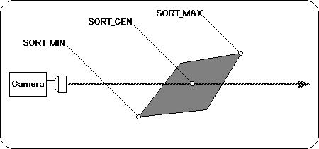
“SORT_BFR” is a special specification and is used when you want to display one polygon above (front) another polygon. Specifically, the display position of the polygon for which "SORT_BFR" is specified is immediately before the polygon registered immediately before that polygon. However, since it is a specification that has meaning for the first time when you want to use two polygons as a group, you will not usually use it much.
Due to the nature of the Z sort method, there is a possibility that the context may become strange depending on how the representative points are taken. See the following example.
<Fig. 7-2 Differences in context depending on representative points>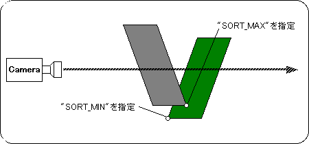
If you specify a representative point as shown above, the actual screen will be as shown below.
<Fig. 7-3 Actual screen>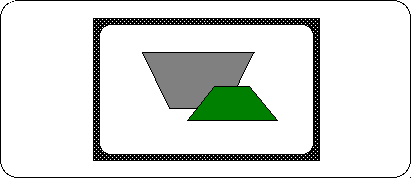
Sega Saturn's texture mapping and so-called texture mapping in general CG have two different properties as shown in Table 7-3.
| Texture mapping | |||
| For Sega Saturn | In the case of general CG | ||
Of texture | Stake | It is possible to paste one texture for one polygon. | You can paste a single texture across multiple polygons. |
Deformation | It also deforms the texture according to the shape of the polygon. | The texture is clipped to the shape of the polygon. | |
<Fig. 7-5 Texture features 1>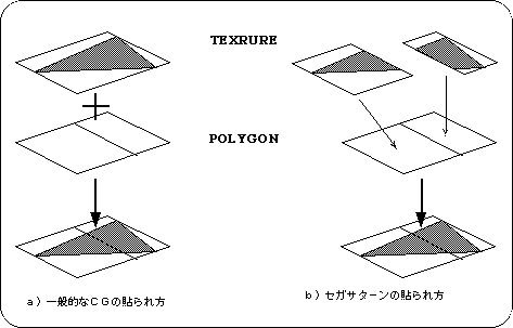
Textures in general CG can be pasted over multiple polygons, but in the case of Sega Saturn, one texture is pasted in correspondence with one polygon. When pasting a texture that spans two or more polygons, it is necessary to divide the texture according to each polygon as shown in Fig. 7-5.
<Fig. 7-6 Texture feature 2>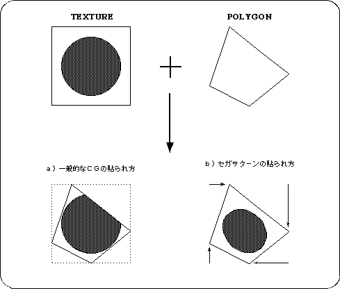
<Fig. 7-7 Texture distortion>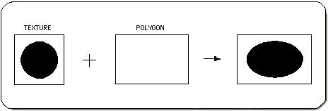
Let's take a look at the sample program (Listing 7-4).
A single textured polygon rotates around the Y axis as a fulcrum.
Here, register two textures in advance.
One is a [SONIC] picture (size: 64 x 64 pixels), and the other is an "AM2" mark (size: 64 x 32 pixels).
/ * ------------------------------------------------ ---------------------- * /
/ * Polygon & Texture * /
/ * ------------------------------------------------ ---------------------- * /
#include "sgl.h"

extern PDATA PD_PLANE;
extern TEXTURE tex_sample [];
extern PICTURE pic_sample [];

#define max_texture 2

void set_texture (PICTURE * pcptr, Uint32 NbPicture)
{
	TEXTURE * txptr;

	for (; NbPicture-> 0; pcptr ++) {
		txptr = tex_sample + pcptr-> texno;
		slDMACopy ((void *) pcptr-> pcsrc,
			(void *) (SpriteVRAM + ((txptr-> CGadr) << 3)),
			(Uint32) ((txptr-> Hsize * txptr-> Vsize * 4) >> (pcptr-> cmode)));
	}
}

void ss_main (void)
{
	static ANGLE ang [XYZ];
	static FIXED pos [XYZ];

	slInitSystem (TV_320x224, tex_sample, 1);
	set_texture (pic_sample, max_texture);
	slPrint ("Sample program 7.4", slLocate (9,2));

	ang [X] = ang [Y] = ang [Z] = DEGtoANG (0.0);
	pos [X] = toFIXED (0.0);
	pos [Y] = toFIXED (0.0);
	pos [Z] = toFIXED (170.0);

	while (-1) {
		slPushMatrix ();
		{
			slTranslate (pos [X], pos [Y], pos [Z]);
			slRotX (ang [X]);
			slRotY (ang [Y]);
			slRotZ (ang [Z]);
			ang [Y] + = DEGtoANG (2.0);
			slPutPolygon (& PD_PLANE);
		}
		slPopMatrix ();

		slSynch ();
	}
}
First, pay attention to line 29.
This is the initialization routine that I used implicitly until now, but the second parameter is different. Here, specify the pointer to the texture table to be passed to SGL. (The actual table is defined in “texture.c”. See Listing 7-5 .) Since we didn't use textures before, we assigned “NULL”.
The 30th line transfers the texture data to V-RAM.
This texture data transfer can be performed at any time after initialization, so you can easily perform techniques such as redrawing textures during the game.
The 12th and subsequent lines are the actual texture data transfer routines.
Here, the start address of the texture table and the number of registered textures are received. Then, the “slDMACopy” function on the 18th line transfers data at high speed using DMA.
The first parameter of this function is the transfer source address, the second parameter is the transfer destination address, and the third parameter is the transfer size.
Next, let's look at the texture data.
#include "sgl.h"
/ ******************************** /
/ * Texture Data * /
/ ******************************** /

TEXDAT sonic_64x64 [] = {/ * Texture data 1 * /
	 0xffff, 0xffff, 0xffff, 0xffff, 0xffff, 0xffff, 0xffff, 0xffff,
					::
					::
				      Omission:
};

TEXDAT am2_64x32 [] = {/ * Texture data 2 * /
	 0xffff, 0xffff, 0xffff, 0xffff, 0xffff, 0xffff, 0xffff, 0xffff,
					::
					::
				      Omission:
};

TEXTURE tex_sample [] = {/ * Table to pass to SGL * /
	TEXDEF (64,64,0),
	TEXDEF (64,32,64 * 64 * 1),
};

PICTURE pic_sample [] = {/ * VRAM transfer table * /
	PICDEF (0, COL_32K, sonic_64x64),
	PICDEF (1, COL_32K, am2_64x32),
};
The part described by the TEXTURE macro is the texture table to be passed to SGL.
Set the size of each texture (horizontal x vertical) and the offset value from the start address of the actual texture data.
Finally, the PICTURE macro part becomes the table for VRAM transfer.
Set the texture number, color mode, and pointer to the texture data, respectively.
Last but not least, let's take a look at the attributes of polygon data.
#include "sgl.h"

#define PN_SONIC 0
#define PN_AM2 1

POINT point_plane [] = {
        POStoFIXED (-40.0, -40.0, 0.0),
        POStoFIXED (40.0, -40.0, 0.0),
        POStoFIXED (40.0, 40.0, 0.0),
        POStoFIXED (-40.0, 40.0, 0.0)
};

POLYGON polygon_plane [] = {
        NORMAL (0.0,0.0,1.0), VERTICES (0, 1, 2, 3)
};

ATTR attribute_plane [] = {
	ATTRIBUTE (Single_Plane, SORT_CEN, PN_SONIC, No_Palet, No_Gouraud, CL32KRGB | MESHoff, sprNoflip, No_Option),
};

PDATA PD_PLANE = {
        point_plane, sizeof (point_plane) / sizeof (POINT),
        polygon_plane, sizeof (polygon_plane) / sizeof (POLYGON),
        attribute_plane
};
 |  |  |
|---|---|---|
| Flat shading | Guro shading |
/ * ------------------------------------------------ ---------------------- * /
/ * Gouraud Shading * /
/ * ------------------------------------------------ ---------------------- * /
#include "sgl.h"

extern PDATA PD_CUBE;

#define GRoffsetTBL (r, g, b) (((b & 0x1f) << 0) | ((g & 0x1f) << 5) | (r & 0x1f))
#define VRAMaddr (SpriteVRAM + 0x70000)

static Uint16 GRdata [6] [4] = {
	{GRoffsetTBL (0, -16, -16), GRoffsetTBL (0, -16, -16),
	  GRoffsetTBL (0, -16, -16), GRoffsetTBL (-16, 15, 0)},
	{GRoffsetTBL (0, -16, -16), GRoffsetTBL (0, -16, -16),
	  GRoffsetTBL (-16, 15, 0), GRoffsetTBL (0, -16, -16)},
	{GRoffsetTBL (-16, 15, 0), GRoffsetTBL (0, -16, -16),
	  GRoffsetTBL (0, -16, -16), GRoffsetTBL (0, -16, -16)},
	{GRoffsetTBL (0, -16, -16), GRoffsetTBL (-16, 15, 0),
	  GRoffsetTBL (0, -16, -16), GRoffsetTBL (0, -16, -16)},
	{GRoffsetTBL (0, -16, -16), GRoffsetTBL (-16, 15, 0),
	  GRoffsetTBL (0, -16, -16), GRoffsetTBL (0, -16, -16)},
	{GRoffsetTBL (-16, 15, 0), GRoffsetTBL (0, -16, -16),
	  GRoffsetTBL (0, -16, -16), GRoffsetTBL (0, -16, -16)}
};

void ss_main (void)
{
	static ANGLE ang [XYZ];
	static FIXED pos [XYZ];

	slInitSystem (TV_320x224, NULL, 1);
	slPrint ("Sample program 7.6", slLocate (9,2));

	ang [X] = DEGtoANG (30.0);
	ang [Y] = DEGtoANG (0.0);
	ang [Z] = DEGtoANG (0.0);
	pos [X] = toFIXED (0.0);
	pos [Y] = toFIXED (0.0);
	pos [Z] = toFIXED (200.0);

	slDMACopy (GRdata, (void *) VRAMaddr, sizeof (GRdata));

	while (-1) {
		slPushMatrix ();
		{
			slTranslate (pos [X], pos [Y], pos [Z]);
			slRotX (ang [X]);
			slRotY (ang [Y]);
			slRotZ (ang [Z]);
			slPutPolygon (& PD_CUBE);
		}
		slPopMatrix ();

		ang [Y] + = DEGtoANG (1.0);

		slSynch ();
	}
}
Now let's look at the attributes.
#include "sgl.h"

#define GRaddr 0xe000

static POINT point_CUBE [] = {
	POStoFIXED (-20.0, -20.0, 20.0),
	POStoFIXED (20.0, -20.0, 20.0),
	POStoFIXED (20.0, 20.0, 20.0),
	POStoFIXED (-20.0, 20.0, 20.0),
	POStoFIXED (-20.0, -20.0, -20.0),
	POStoFIXED (20.0, -20.0, -20.0),
	POStoFIXED (20.0, 20.0, -20.0),
	POStoFIXED (-20.0, 20.0, -20.0)
};

static POLYGON polygon_CUBE [] = {
	NORMAL (0.0, 0.0, 1.0), VERTICES (0, 1, 2, 3),
	NORMAL (-1.0, 0.0, 0.0), VERTICES (4, 0, 3, 7),
	NORMAL (0.0, 0.0, -1.0), VERTICES (5, 4, 7, 6),
	NORMAL (1.0, 0.0, 0.0), VERTICES (1, 5, 6, 2),
	NORMAL (0.0, -1.0, 0.0), VERTICES (4, 5, 1, 0),
	NORMAL (0.0, 1.0, 0.0), VERTICES (3, 2, 6, 7)
};

static ATTR attribute_CUBE [] = {
	ATTRIBUTE (Single_Plane, SORT_MIN, No_Texture, C_RGB (31,16,31), GRaddr, MESHoff | CL_Gouraud, sprPolygon, No_Option),
	ATTRIBUTE (Single_Plane, SORT_MIN, No_Texture, C_RGB (31,16,31), GRaddr + 1, MESHoff | CL_Gouraud, sprPolygon, No_Option),
	ATTRIBUTE (Single_Plane, SORT_MIN, No_Texture, C_RGB (31,16,31), GRaddr + 2, MESHoff | CL_Gouraud, sprPolygon, No_Option),
	ATTRIBUTE (Single_Plane, SORT_MIN, No_Texture, C_RGB (31,16,31), GRaddr + 3, MESHoff | CL_Gouraud, sprPolygon, No_Option),
	ATTRIBUTE (Single_Plane, SORT_MIN, No_Texture, C_RGB (31,16,31), GRaddr + 4, MESHoff | CL_Gouraud, sprPolygon, No_Option),
	ATTRIBUTE (Single_Plane, SORT_MIN, No_Texture, C_RGB (31,16,31), GRaddr + 5, MESHoff | CL_Gouraud, sprPolygon, No_Option),
};

PDATA PD_CUBE = {
	point_CUBE, sizeof (point_CUBE) / sizeof (POINT),
	polygon_CUBE, sizeof (polygon_CUBE) / sizeof (POLYGON),
	attribute_CUBE
};
Also pay attention to the sixth parameter “Mode”.
When using Gouraud shading, it is necessary to specify “CL_Gouraud” here. When not using Gouraud shading, specify the macro "No_Gouraud" for the 5th parameter, "Gouraud".
| group | macro | Contents |
|---|---|---|
| [1] | No_Window | Unrestricted by Window (default) |
| Window_In | Display inside the Window | |
| Window_Out | Display outside the window | |
| [2] | MESHoff | Normal display (default) |
| MESHon | Display as a mesh | |
| [3] | ECdis | Disable End Code |
| ECenb | Enable End Code (default) | |
| 【Four】 | SPdis | Also show transparent pixels (default) |
| SPenb | Do not show transparent pixels | |
| 【Five】 | CL16Bnk | 16 color bank mode (default) |
| CL16Look | 16-color look-up table | |
| CL64Bnk | 64-color color bank mode | |
| CL128Bnk | 128 color color bank mode | |
| CL256Bnk | 256 color bank mode | |
| CL32KRGB | 32768 color RGB mode | |
| [6] | CL_Replace | Overwrite (standard) mode (default) |
| CL_Shadow | Shadow mode | |
| CL_Half | Semi-brightness mode | |
| CL_Trans | Semi-transparent mode | |
| CL_Gouraud | Gouraud shading mode | |
| [7] | HSSon | Use high speed shrink |
| HSSoff | Do not use high speed shrink (default) | |
| [8] | MSBon | Set up MSB when writing to framebuffer |
| MSBoff | Do not set MSB when writing to framebuffer (default) |
Group [5] is for specifying the color mode of the texture, so if you do not use the texture, be sure to set it to the default (“CL_16Bnk” or not specified). If you specify any other mode here, the polygons will not be displayed.
As an exception to group [6], “CL_Gouraud | -CL_Half” and “CL_Gouraud | -CL_Trans” can be used. Please use it when you want to use semi-brightness Gouraud shading and semi-transparent Gouraud shading.
When using Gouraud shading, it is necessary to set “CL_Gouraud” here as well as setting the 5th parameter.
When using semi-brightness, translucency, and Gouraud shading, polygons are only supported in RGB direct mode and textures are only supported in 32768 color RGB mode. Please note that it cannot be displayed correctly with other settings.
| macro | Contents |
|---|---|
| sprNoflip | Display textures normally |
| sprHflip | Flip the texture left and right |
| sprVflip | Flip the texture upside down |
| sprHVflip | Flip the texture up / down / left / right |
| sprPolygon | Show polygons |
| sprPolyLine | Show polyline |
| sprLine | Display a straight line using the first two points |
| macro | Contents |
|---|---|
| UseLight | Perform light source calculation |
| UsePalette | Indicates that the polygon color is in palette format |
| UseNearClip | 4 Do not display when the vertices go out of the screen specified by slWindowClipLevel |
| UseDepth | Calculate depth skew with parallel light sources |
| Use Gouraud | Calculate light source with real-time goo (valid only for slPutPolygonX) |
| Functional type | Function name | Parameters | function |
|---|---|---|---|
| void | slDMACopy | Src, dst, cnt | Block transfer using CPU DMA |
★ SGL User's Manual ★ PROGRAMMER'S STRUCT