SGL User's ManualPROGRAMMER'S STRUCT
BackForward

8-9. Rotating scroll screen

The rotation scroll screen "RBG0" can be enlarged / reduced and rotated.
Also, although the idea is different from normal scrolling, it is possible to move the scroll vertically and horizontally.
Here, we will explain the movement, enlargement / reduction, and rotation functions of the rotation scroll together with the sample program.

Rotation scroll movement

The movement of the rotary scroll is also realized as a change in the scroll display position.
By using the function "slLookR", it is possible to make the scroll appear to move up, down, left and right to the monitor.

Figure 8-21 Moving image of rotary scroll

Rotation scroll screen enlargement / reduction

In SGL, it is also possible to enlarge / reduce the rotation scroll screen. The enlargement / reduction of the rotating scroll screen is different from the enlargement / reduction of the normal scroll screen, and it is always possible to enlarge / reduce at an arbitrary magnification.
In addition, in the case of the rotary scroll screen, it can be used in combination with the scroll rotation operation, enlargement / reduction operation, and movement operation described later.
If you want to zoom in / out the rotary scroll screen in SGL, use the library function "slZoomR".

[Void slZoomR (FIXED scale_x, FIXED scale_y);]
The rotation scroll screen "RBG0" is enlarged / reduced and the current state is saved in the current rotation parameter (the current parameter can be switched by the function "slCurRpara").
Substitute the scroll vertical and horizontal magnifications as reciprocals for the parameters.
For example, if you want to enlarge it by 2 times, substitute 1/2 for the parameter, and if you want to reduce it by 1/2, substitute 2.
For rotary scrolling, scaling can always be set at any magnification.

Rotate scroll screen rotation

In Sega Saturn, scroll rotation with arbitrary axis and arbitrary angle value is possible for the rotation scroll screen (the figure below is an image model).

Figure 8-22 Scroll rotation image

● 2D rotation (Z-axis rotation)
If you want to perform 2D rotation operation (Z-axis rotation) of the rotation scroll screen with SGL, use the library function "slZrotR".
The point at the center of rotation (one point on the scroll map) uses the point set by the library function “slDispCenterR”.

[Void slZrotR (ANGLE z_angle);]
Rotate Scroll screen "RBG0" is rotated with respect to the Z axis.
For the parameter, specify the Z-axis rotation angle of the current rotation parameter.
For the rotation angle, substitute the absolute rotation angle value, not the rotation angle value from the current state.
(Current parameters can be switched with the function "slCurRpara").
Also, the center of rotation uses the points set by the library function “slLookR”.

Figure 8-23 Actual operation of scroll rotation

Precautions when using functions
The functions "slZrotR", "slZoomR", and "slLookR" used for the conversion operation of the rotation scroll have the same rotation parameters as the function "slScrMatSet" that also performs various conversion operations (including 3D rotation) of the rotation scroll. Please note that it cannot be used together.
This is because the function group rewrites a specific area of the rotation parameter, while the function group described later rewrites the entire rotation parameter.

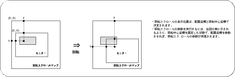
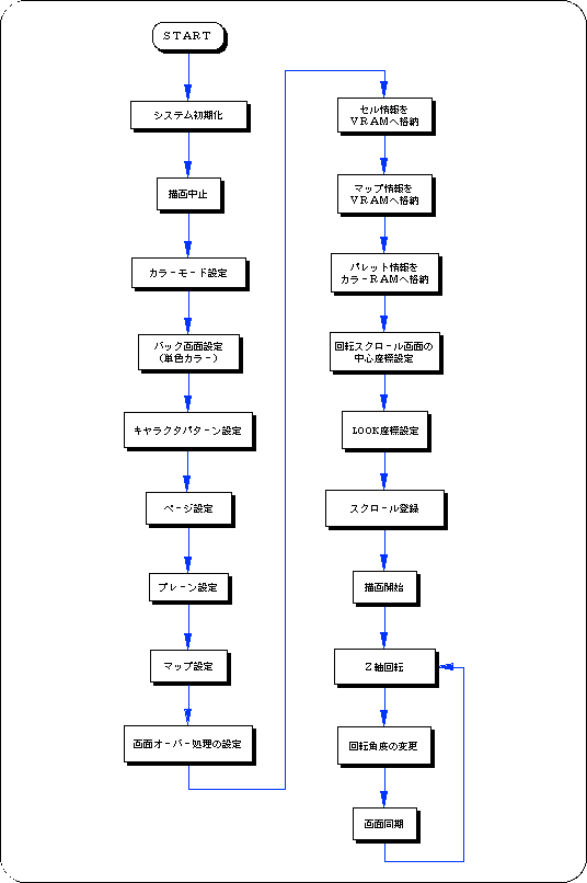
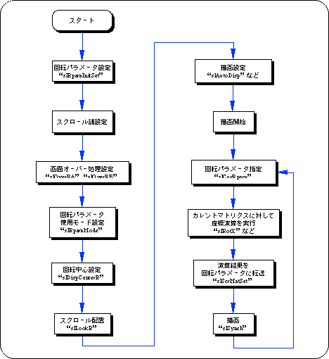
The following sample program (Listing 8-5) is an example of actually rotating the rotation scroll screen using the SGL library function.

Listing 8-5 sample_8_9_1: 2D scroll rotation

/ * ------------------------------------------------ ---------------------- * /
/ * Graphic Rotation * /
/ * ------------------------------------------------ ---------------------- * /
#include "sgl.h"
#include "ss_scrol.h"

#define RBG0_CEL_ADR VDP2_VRAM_A0
#define RBG0_MAP_ADR VDP2_VRAM_B0
#define RBG0_COL_ADR (VDP2_COLRAM + 0x00200)
#define RBG0_PAR_ADR (VDP2_VRAM_A1 + 0x1fe00)
#define BACK_COL_ADR (VDP2_VRAM_A1 + 0x1fffe)

void ss_main (void)
{
	ANGLE yama_angz = DEGtoANG (0.0);
	FIXED posx = toFIXED (128.0), posy = toFIXED (64.0);
	
	slInitSystem (TV_320x224, NULL, 1);
	slTVOff ();
	slPrint ("Sample program 8.9.1", slLocate (9,2));

	slColRAMMode (CRM16_1024);
	slBack1ColSet ((void *) BACK_COL_ADR, 0);

	slRparaInitSet ((void *) RBG0_PAR_ADR);
	slCharRbg0 (COL_TYPE_256, CHAR_SIZE_1x1);
	slPageRbg0 ((void *) RBG0_CEL_ADR, 0, PNB_1WORD | CN_10BIT);
	slPlaneRA (PL_SIZE_1x1);
	sl1MapRA ((void *) RBG0_MAP_ADR);
	slOverRA (2);
	Cel2VRAM (yama_cel, (void *) RBG0_CEL_ADR, 31808);
	Map2VRAM (yama_map, (void *) RBG0_MAP_ADR, 32, 16, 1, 0);
	Pal2CRAM (yama_pal, (void *) RBG0_COL_ADR, 256);

	slDispCenterR (toFIXED (160.0), toFIXED (112.0));
	slLookR (toFIXED (128.0), toFIXED (64.0));

	slScrAutoDisp (NBG0ON | RBG0ON);
	slTVOn ();

	while (1) {
		slZrotR (yama_angz);
		yama_angz + = DEGtoANG (1.0);
		slSynch ();
	} 
}

Flow 8-6 sample_8_9_1: 2D rotation of scroll

● 3D rotation using the current matrix
In order to perform 3D rotation operation (rotation of all axes) of the rotation scroll screen using the current matrix in SGL, it is necessary to follow the procedure below.

1) Rotation scroll settings
Complete the settings required when using the rotation scroll, such as rotation parameter settings, screen over processing, and coefficient table settings.

2) Coordinate calculation
First, execute the 3D rotation operation to be multiplied by the rotation scroll on the current matrix.
Use the same functions such as “slRorX”, “slTranslate”, and “slScale”.
However, the operation order of rotation / move / enlargement / reduction operations is the reverse of the normal coordinate conversion operation (see "Chapter 4: Coordinate Conversion" for the conversion operation order).
In addition, the scroll coordinate system is the left-handed coordinate system with the positive and negative of the Z axis reversed, but it looks exactly the same because it is captured as an image of the monitor rotating and moving with respect to scrolling.
If you want to perform the coordinate conversion operation using the same matrix operation procedure as the normal coordinate conversion operation, use the function “slScrMatConv” before transferring the matrix data.
The function “slScrMatConv” converts the current matrix converted by the normal coordinate conversion procedure into the scroll coordinate conversion matrix and makes it the current matrix.

[Void slScrMatConv (void);]
Converts the current matrix to scroll coordinate conversion data and replaces the current matrix.
As a matter of course, if the function is used for the current matrix after executing the scroll coordinate conversion operation, the current matrix will be replaced with the normal coordinate conversion matrix.

3) Transfer the calculation result to the rotation parameter
Transfers the result of the coordinate calculation performed on the current matrix to the rotation parameter.
The rotation scroll transforms and draws the calculation result based on the transferred rotation parameter data.
Use the function “slScrMatSet” to transfer data.

[Void slScrMatSet (void);]
Transfers the current matrix data to the current rotation parameters.
Use it to transfer the current matrix that has undergone coordinate conversion operations according to the rotation scroll.

Flow 8-7 Procedure of 3D rotation operation using current matrix

● Control of zoom ratio using coefficient table
When performing a 3D rotation operation on a rotating scroll, the rotating scroll scales the scroll according to the depth of the scroll. Normally, this scale ratio is calculated based on each parameter used for 3D coordinate calculation such as perspective conversion to deform the scroll, but this deformation ratio is set in advance for each line or dot, and the scroll is deformed. It is available at runtime and is called the coefficient table.
The following two functions are required to use the coefficient table.

1) Creation of coefficient table
First of all, it is necessary to reserve an area for the coefficient table in the VRAM area.
Be sure to create the coefficient table in VRAM.
In addition, the coefficient table occupies one bank in the VRAM area. This is because the coefficient table refers to the VRAM area with the maximum number of accesses per bank (8 times).

[Void slMakeKtable (void * adr);]
Creates a coefficient table to be used in 3D rotation operation at the specified address.
Assign the start address of the area for creating the coefficient table to the parameter.
Also, the coefficient table must always be allocated in the VRAM area.

2) Setting the coefficient table usage mode
When using the area specified as the coefficient table as the coefficient table, it determines the usage mode of how to use the coefficient table.

[Void slKtableRA, RB (void * table_adr, Uint16 mode);]
Specify the address of the coefficient table to be used, and further determine the content of the coefficient table to be used.
Substitute the start address of the coefficient table and the value shown in the figure below (or operator "|" can be used for concatenation) to indicate the mode of use of the coefficient table.
The function "slKtableRA" sets the coefficient table used by rotation parameter A, and the function "slKtableRB" sets the coefficient table used by rotation parameter B.

Figure 8-24 Parameter assignment value (mode) of “slKtableRA, RB”
Table use: [K_OFF | K_ON] |
Coefficient data size: [K_2WORD | K_1WORD] |
Coefficient mode: [K_MODE0 | K_MODE1 | K_MODE2 | K_MODE3] |
Line color: [K_LINECOL] |
Deformation unit: [K_DOT | K_LINE] |
Fixed coefficient: [K_FIX] |

note)
If fixed coefficient is specified for the parameter, the coefficient table is assumed to be prepared in advance and the calculation of the coefficient table in real time is not executed.

reference
For details on the coefficient table, refer to "HARDWARE MANUAL vol.2: VDP2 User's Manual".

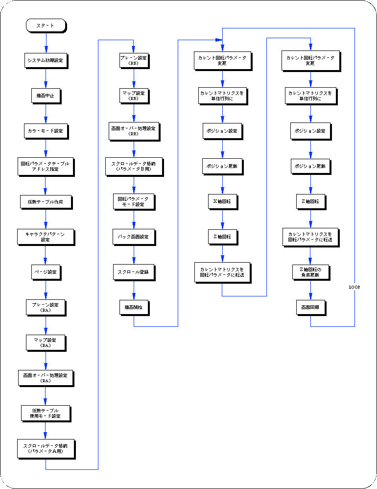
Listing 8-6 sample_8_9_2: 3D rotation

#include "sgl.h"
#include "ss_scrol.h"

#define RBG0RB_CEL_ADR (VDP2_VRAM_A0)
#define RBG0RB_MAP_ADR (VDP2_VRAM_B0)
#define RBG0RB_COL_ADR (VDP2_COLRAM + 0x00200)
#define RBG0RA_CEL_ADR (RBG0RB_CEL_ADR + 0x06e80)
#define RBG0RA_MAP_ADR (RBG0RB_MAP_ADR + 0x02000)
#define RBG0RA_COL_ADR (RBG0RB_COL_ADR + 0x00200)
#define RBG0_KTB_ADR (VDP2_VRAM_A1)
#define RBG0_PRA_ADR (VDP2_VRAM_A1 + 0x1fe00)
#define RBG0_PRB_ADR (RBG0_PRA_ADR + 0x00080)
#define BACK_COL_ADR (VDP2_VRAM_A1 + 0x1fffe)

void ss_main (void)
{
	FIXED posy = toFIXED (0.0);
	ANGLE angz = DEGtoANG (0.0);
	ANGLE angz_up = DEGtoANG (0.0);

	slInitSystem (TV_320x224, NULL, 1);
	slTVOff ();
	slPrint ("Sample program 8.9.2", slLocate (9,2));

	slColRAMMode (CRM16_1024);

	slRparaInitSet ((void *) RBG0_PRA_ADR);
	slMakeKtable ((void *) RBG0_KTB_ADR);
	slCharRbg0 (COL_TYPE_256, CHAR_SIZE_1x1);
	slPageRbg0 ((void *) RBG0RB_CEL_ADR, 0, PNB_1WORD | CN_12BIT);
	slPlaneRA (PL_SIZE_1x1);
	sl1MapRA ((void *) RBG0RA_MAP_ADR);
	slOverRA (0);
	slKtableRA ((void *) RBG0_KTB_ADR, K_FIX | K_DOT | K_2WORD | K_ON);
	Cel2VRAM (tuti_cel, (void *) RBG0RA_CEL_ADR, 65536);
	Map2VRAM (tuti_map, (void *) RBG0RA_MAP_ADR, 64, 64, 2, 884);
	Pal2CRAM (tuti_pal, (void *) RBG0RA_COL_ADR, 160);

	slPlaneRB (PL_SIZE_1x1);
	sl1MapRB ((void *) RBG0RB_MAP_ADR);
	slOverRB (0);
	slKtableRB ((void *) RBG0_KTB_ADR, K_FIX | K_DOT | K_2WORD | K_ON);
	Cel2VRAM (sora_cel, (void *) RBG0RB_CEL_ADR, 28288);
	Map2VRAM (sora_map, (void *) RBG0RB_MAP_ADR, 64, 20, 1, 0);
	Pal2CRAM (sora_pal, (void *) RBG0RB_COL_ADR, 256);

	slRparaMode (K_CHANGE);

	slBack1ColSet ((void *) BACK_COL_ADR, 0);

	slScrAutoDisp (NBG0ON | RBG0ON);
	slTVOn ();

	while (1)
	{
		slCurRpara (RA);
		slUnitMatrix (CURRENT);
		slTranslate (toFIXED (0.0), toFIXED (0.0) + posy, toFIXED (100.0));
		posy-= toFIXED (5.0);
		slRotX (DEGtoANG (-90.0));
		slRotZ (angz);
		slScrMatSet ();

		slCurRpara (RB);
		slUnitMatrix (CURRENT);
		slTranslate (toFIXED (160.0), toFIXED (155.0), toFIXED (100.0));
		slRotZ (angz);
		slScrMatSet ();

		angz_up + = DEGtoANG (0.5);
		angz = (slSin (angz_up) >> 4);

		slSynch ();
	} 
}

Flow 8-8 sample_8_9_2: 3D rotation


BackForward
SGL User's ManualPROGRAMMER'S STRUCT
Copyright SEGA ENTERPRISES, LTD., 1997